There are mainly two techniques or methods to control the output voltage of a chopper: Time Ratio Control Method and Current Limit Control. The output voltage of chopper depends on the duty cycle. By changing the duty cycle, the output voltage can be varied. Both the methods, employ some technique to vary the duty cycle. In this article, we will focus on Time Ratio Control method for voltage control of chopper and discuss Pulse Width Modulation and Frequency Modulation schemes.
Time Ratio Control Method:
Time Ratio Control is the method of controlling the output voltage of chopper by changing the ON (TON) period of chopper while keeping the chopping frequency constant or keeping the TON or TOFF constant and varying the chopping frequency. Change in chopping frequency essentially means that the total time period T is changed. In this way, the duty cycle (α) is varied to get the controlled output voltage.
As we know that, the output voltage of chopper is given as
Vo = αVs ……….(1)
Therefore, changing α while keeping T constant will result in change in Vo.
Time Ratio Control is realized in two different strategies called the Constant Frequency System and Variable Frequency System.
Constant Frequency System or Pulse Width Modulation Technique:
In this technique, the time period of chopper is maintained constant and change in duty cycle is achieved by changing TON period. Since, time period is constant, chopping frequency will be constant, hence this scheme is called constant frequency system.
It should be noted that, by changing the ON, the width of output voltage pulse is adjusted to have the desired output voltage. This is the reason; this method of voltage control of chopper is also known as Pulse Width Modulation Scheme.
Figure below illustrate the principle of Pulse Width Modulation Scheme / Constant Frequency System.
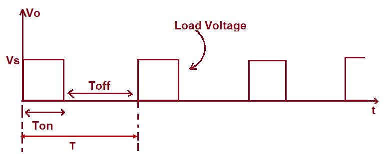
It may be seen from the above figure that, the ON period is around (1/4)th times the total time period. Hence, the duty cycle α = (TON / T) = (1/4). Therefore, the output voltage is given from (1) as shown below.
Vo = (Vs/4)
= 25% of Vs
Thus, output voltage is 25% of input DC voltage. Let us now increase the TON time such that it is 75% of the total time period T. This is shown below.
In the above figure, TON = (3T/4). Duty cycle from this waveform is, therefore, (3/4). This simply means that, the output voltage Vo will be 75% of the input source voltage Vs.
Thus, we have seen that, changing TON leads to change in duty cycle “α” and hence output voltage Vo. Ideally α can be varied from ZERO to UNITY. Therefore, output voltage Vo can be controlled from ZERO to source voltage Vs.
Variable Frequency System or Frequency Modulation Scheme:
In this scheme, the chopping frequency is varied (hence, chopping time period T) either by maintaining ON time TON or OFF time TOFF. Therefore, the duty cycle of chopper is varied. This method of controlling duty cycle α is also called Frequency Modulation Scheme.
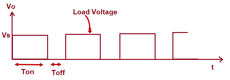
Figure below illustrate the principle of frequency modulation. In this figure, TON is kept constant but T is varied.

In the first figure, TON = T/4 so that duty cycle α = 0.25. Therefore, the output voltage Vo will become 0.25Vs from (1). In the lower diagram, TON = 3T/4 so that duty cycle α = 0.75. Therefore, the output voltage will become 0.75Vs from (1).
In the same way, the TOFF period may be varied to get controlled duty cycle α and hence controlled output voltage. Frequency modulation scheme has some disadvantage as compared to pulse width modulation scheme of voltage control of chopper. It is described below.
Disadvantage of Frequency Modulation Scheme:
Following are the disadvantage of frequency modulation scheme:
- The chopping frequency has to be varied over a wide range for control of output voltage in frequency modulation. Filter design for such wide frequency variation is quite difficult.
- A wide frequency variation is required for control of chopper duty cycle. Therefore, there is always a chance of interference with signaling and telephone lines in frequency modulation scheme.
- The large off time in this scheme may make the load current discontinuous which is undesirable.
Whether Pulse Width Modulation or Frequency Modulation scheme is better?
Pulse Width Modulation (PWM) scheme is better than variable frequency scheme. However, PWM technique has a limitation. In PWM, ON period can not be reduced near to zero. Therefore, low range of duty cycle is not achievable in this technique. However, this can be achieved by increasing the chopping period or decreasing the chopping frequency of chopper.