Current Limit Control is one of the output voltage control strategy of chopper. In this method, the ON and OFF time of chopper circuit is governed by the previously set value of load current. This technique is different form Time Ratio Control method.
In this technique, the chopper is switched ON when the load current reaches the minimum set value and it is switched OFF when load current becomes equal to the maximum set value. The maximum and minimum set value of load current are Iomax and Iomin respectively. These two values are independently set.
Figure below shows the output current waveform of a chopper.
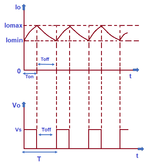
In this figure, the current rises from its minimum value Iomin to maximum value Iomax during the chopper ON time. However, the load current decays to Iomin from its peak value Iomax during the chopper OFF time. The chopper is switched OFF when current Io becomes Iomax whereas it is switched ON when current reaches Iomin. ON and OFF period of chopper is shown in the figure. Profile of load current shows that it fluctuates between Iomax to Iomin and hence, load current is always continuous.
It may be noted that in Current Limit Control scheme, the duty cycle is adjusted in such a way that load current never becomes discontinuous. Switching frequency (f) of chopper can be controlled by setting the value of Iomax and Iomin. As the output voltage of chopper is given as
Vo = f.(TONVs)
Therefore, controlling the chopping frequency results in regulated output voltage of chopper.
Carefully observe the load current waveform. As expected, the load current should be a pure DC but you may see that the load current is not a pure DC rather it is having some ripple. The value of ripple content is equal to (Iomax – Iomin). To reduce this ripple content, the chopping frequency has to be increased which in turn lead to more switching losses.
Current limit control involves feedback loop, the trigger circuitry for the chopper is, therefore, more complex. This is the reason; Pulse Width Modulation technique is commonly chosen control strategy for the power control in chopper circuit.