Parallel operation of three phase transformer is very common in three phase power generation, transmission and distribution. It is advantageous to use two or more Transformer units in parallel instead of using a single large unit. This offers flexibility for maintenance as well as operation.
Advantage of Parallel Operation of Three Phase Transformers
- It increases the reliability of supply system. Let us try to understand how this happens. Suppose a fault occurs in any one of the Transformer unit. In such case, the faulty transformer may be taken out of service while the remaining transformers will feed the power supply. If there were only one large transformer unit is installed for supplying the load, the supply to the entire load will be interrupted during breakdown of the transformer. Thus the reliability of supply system is increased by parallel operation of transformers.
- The size of transformer increases with the increase of its rating. Therefore, a larger transformer will be bigger in size. Therefore, its transportation form manufacturer to the Site will be difficult. Whereas, transportation and installation of small sized transformers are comparatively easy.
- The maintenance opportunity in case of parallel operation is increases. One or more transformers may be taken under maintenance while the remaining transformers will supply the load at reduced power.
Condition for Parallel Operation of Three Phase Transformers
Following are the necessary conditions for parallel operation of 3 phase transformers:
- The line voltage ratio of the transformers must be same.
- The transformers should have equal per unit leakage impedance. (You may read per unit system)
- The ratio of equivalent leakage reactance to equivalent resistance should be same for all the transformers.
- The transformers should have the same polarity.
The above four conditions are also applicable for parallel operation of single phase transformers. Apart from the above four condition, there exists two more conditions which should be fulfilled for parallel operation of three phase transformers:
- The relative phase displacement between the secondary line voltages of all transformers should be zero. This means that transformers to be connected in parallel must belong to same Group number like Yy0 and Dd0 belong to same group number viz. Group 1.
- The phase sequence of secondary line voltages of all the transformers should be same.
There may arise several questions in your mind at this point of time. Though I can’t guess all those but can definitely guess some of them. Some of the common questions are explained below.
Why relative phase displacement between the secondary line voltages should be zero? Or what would happen if transformers of different group numbers are connected in parallel?
Let us assume that two transformers of different group numbers are connected in parallel as shown in figure below.
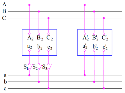
The secondary line voltages of these transforms will not be in phase rather they will be displaced from each other as shown in figure below.
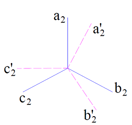
A voltage across the switch S1, S2 & S3 is developed due to this displacement in secondary voltages. The voltage across the switches S1, S2 and S3 will be equal to the length of phasor joining (a2, a2’), (b2, b2’) & (c2,c2’) respectively. Due to this voltage when these switches are closed, a large circulating current will start flowing through the secondary winding. This may damage the transformer. Therefore it is essential that transformers belong to the same group number so that the relative phase displacement between the secondary line voltages is zero. However, the transformers of group number 3 &4 can be successfully operated in parallel.
Why phase sequence should be equal for parallel operation of 3 phase transformers?
The phase sequence of secondary line voltages of all the transformers should be same. If the phase sequence is same, there will not be any voltage across the switches S1, S2 and S3. However, an improper phase sequence may result in complete damage of the transformer. Let us consider the figure below.
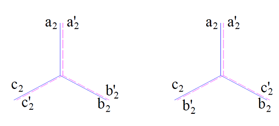
In the left figure, the phase sequence of secondary line voltage of both the transformers are correct> therefore, zero voltage will be developed across the switch S1, S2 and S3. But in rightmost figure, the phase sequence is reversed for second transformer. Under this case, no voltage will be there across S1, but voltage equal to line voltage (c2-b2’ and b2-c2’) will be developed across the switches S2 and S3. These switches may not be designed to withstand this voltage. Therefore, parallel operation is not possible.
what will happen to the fault level in case I operate 2 Nos 3 phase 3300 KVA Transformers in parallel?
The level of fault current depends on the configuration of system and impedance up to the point of fault. So until configuration and impedances are not known, the level of fault current is difficult to calculate. But still, I will post on the effect on fault level by parallel operation of transformers.
Can you explain exactly “why” voltage develops across switches when transformer with different phase shifts are connected that in turn cause circulating currents? Is it because the voltages when in same phase cancel each other out and hence no circulating currents?
The primary side of transformer is fixed by supply line. However, due to difference in vector group, the secondary voltages will have phase displacement which means that there will be a voltage difference. Hence, a circulating current will flow.
Sir if 2 nos 3 ph 33/.416 kv 250 kva TF used in parallel from common feeder with rewirable fuses and secondary connected with common load / busbar and any one fuse of one TF melts for any reason what will there be any damage . And what protection can be given .
132/11KV Three Phase, Capacity of 1st TF is 20/26MVA & 2nd 37/40 MVA Power Transformer, But the Vector Group of both Transformers are different. Impedance of of first TF is 12.8 on normal Tap & 2nd TF Impedance is 12.4. The LV Side of both TF can be connected for Aux: Supply of Power Transformer.
At the end of the paragraph “Read Aux: Supply” of Power House Instead of Power Transformer. Question raised at1.02 pm dated March 11, 2021
Thanks