Phase Sequence Indicator is an instrument which identifies the phase sequence of three phase supply system. Phase sequence or often called phase rotation of 3 phase supply system is defined as the sequence or order in which voltage in R, Y and B phase is attains their maximum value. Normally the phase sequence is RYB. This means, first R phase voltage attains its peak value followed by Y and B phases. This phase sequence is determined by this indicator.
It should be noted that Phase sequence meter or indicator only identified the phase sequence. It does not explicitly determine whether a particular wire is R phase, Y phase or B phase.
Working principle of Phase Sequence Indicator
There are mainly two types of Phase Sequence Indicator: Rotating Type and Static Type
Rotating Type Phase Sequence Indicator
Rotating type phase sequence indicator is very common. It consists of a disc on which an arrow is marked. This indicator is having three lead: Red, Yellow and Blue. When these three leads R, Y and B are connected to a three phase supply, the disc starts rotating. If the disc rotates in the direction of marked arrow, the phase sequence of supply is then RYB. But if the disc rotates in a direction opposite to marked arrow, the phase sequence of supply is then not RYB rather it is YRB i.e. reversed. Figure below shows a rotating type indicator.
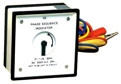
Note: Carefully observe the voltage rating of the indicator shown in above figure. It clearly shows that this indicator is designed for 50-500 V AC. Therefore, it should be used for phase sequence identification for 415 V three phase AC systems or lower. Where the voltage is more than 500 V, this indicator may be used with secondary of potential transformer (potential transformer secondary phase to phase voltage is normally 110 V AC).
The working principle of rotating type phase sequence indicator is same as that of three phase induction motor. When three phase supply is connected to the indicator, a rotating magnetic field is produced. This rotating magnetic field links with the aluminium disc of instrument to create eddy current in it. This eddy current in aluminium disc interacts with the rotating magnetic field and produces torque. This torque causes the rotation of aluminum disc in the direction of rotating magnetic field. As the direction of rotating magnetic field is governed by the phase sequence of supply voltage, therefore the aluminuim disc will rotate in the direction of phase rotation i.e. phase sequence of supply.
Static Type Phase Sequence Indicator
In this type of indicator, there is no rotating part. Figure below shows a typical circuit diagram of a static type phase sequence indicator.
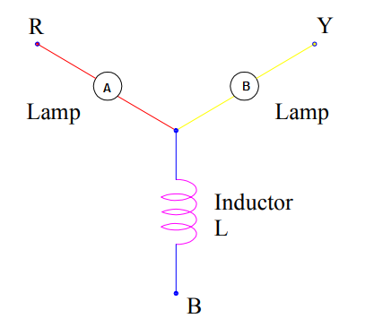
Two lamps are connected in two different phases i.e. one in R phase and another in Y phase. When three phase supply is connected to the terminals of this indicator, these lamps stars glowing. If the brightness of lamp B is more than that of lamp A, the phase sequence of supply is then RYB. But if the brightness of lamp A is more, the supply phase sequence is then YRB.
Let us now understand how the brightness of lamp is related with supply phase sequence. Let the supply phase sequence is RYB. Therefore the supply voltages may be written as
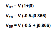
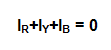
This voltage will cause flow of current IR, IY and IB in R, Y and B phase respectively in such a way that
By solving the above equation, we get
![]()
Thus the current in R phase is only 27% of the current flowing in the Y phase. As both the lamps are identical, therefore lamp B will be brighter than lamp A. This principle is issued for phase identification in phase sequence indicator.
There is one another type of phase sequence indicator, wherein Neon lamps are used in conjunction with series resistance as shown in figure below.
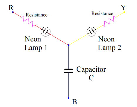
Series resistance limits the current flow through the neon lamps. This is important to protect the neon lamps from getting damage due to excess voltage.
If the supply voltage with RYB phase sequence is connected with this indicator, lamp 1 will glow and lamp 2 will not glow. Lamp 2 will glow and lamp 1 won’t glow if the supply phase sequence is YRB.
Why phase sequence is important or why we should know the phase sequence?
Three phase supply system is very common in industries which feed different kinds of loads. LT Motor is one such example where three phase 415 V AC supply is used for its operation. As per IEC/IS 60034-8 “Terminal markings and direction of rotation”, when U, V and W winding of a motor is connected with R, Y and B phase respectively, the motor shaft will rotate in clockwise direction when viewed from driving end. This means, if correct phase sequence is applied to the motor terminals, the direction of rotation will be clockwise. But when the phase sequence is opposite i.e. YRB, the motor will rotate in counter-clockwise direction.
Thus before carrying out termination at motor terminals, identification of phase sequence is very important. If phase rotation of incomer supply is not correct, the motor (coupled with load like pump) will rotate in opposite direction which in turn may lead to damage of coupled load.
IR+IY+IB=0.
IR/1Y=0.27
HOW GIVE CALCULATIONS
Could not understand your question. Kindly elaborate in detail.