What is Bridge Rectifier?
Bridge Rectifier is a full wave rectifier which converts sinusoidal AC input to DC. This circuit comprises of four diodes which are so connected that two diodes conducts during positive cycle of supply input whereas remaining two conducts during the negative half cycle. A full wave rectifier is one which converts both positive & negative half cycle of input AC supply voltage into DC voltage.
Circuit Diagram of Bridge Rectifier
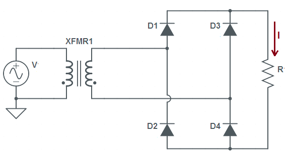
Figure below depicts a simple circuit diagram of full wave bridge rectifier.
Working Principle of Bridge Rectifier
The working principle of bridge rectifier is based on the fact that; during positive half cycle of supply voltage V, diagonally opposite diodes D1 and D4 becomes forward biased and hence conduct. Subsequently, current starts flowing through the load resistance R from transformer secondary to D1 – R – D4 – transformer secondary. Similarly during the negative half cycle, diodes D2 and D3 becomes forward biased and hence conducts. Thereby current through the resistance R starts to flow in the direction shown in the figure. Figure below shows the waveform of output current or current flowing through the load resistance R.
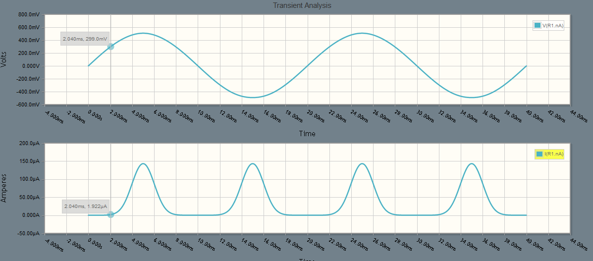
In the above figure, it can be seen that the current flow is unidirectional. It may also be noticed that, diodes D1 & D4 are not conducting for 2 ms. This is because of the requirement of cut-in voltage of diodes. Normally the value of cut-in voltage for Silicon and Germanium diodes are 0.6 and 0.2 V respectively. This means, a silicon diode will not start to conduct until the value of forward biased voltage exceeds 0.6 V. Similarly, a Germanium diode will start conducting if the value of forward biased voltage is more than 0.2 V. If you zoom the above figure, you will notice that the value of cut-in voltage for diodes used to make the bridge rectifier is around 0.3 V. But this is not a universal truth. Here we have used diode having this much of cut-in voltage. You may use some different type of diode which may have different value of cut-in voltage. But whatever is the type, there will definitely be a cut-in voltage requirement and hence the output current waveform will have the same nature as shown in the above figure.
It can also be noticed that load current is flowing for both positive and negative half cycle of the supply voltage. This is the reason, this type of circuit is also called full wave bridge rectifier.
Ripple Factor of Bridge Rectifier
The value of ripple factor for bridge rectifier is 0.482. In fact, value of ripple factor only depends on the wave shape of output current or load voltage waveform. It doesn’t depend on the circuit configuration. Thus its value will be same for center tapped and bridge rectifier as their output waveform is same. You are requested to read “Center Tapped Full wave Rectifier” for reading the calculation part of ripple factor.
Form Factor
The value of form factor for bridge rectifier is 1.11. In fact, its value is same for center tapped and bridge rectifier since the rms and average value of load current for both types of full wave rectifier is same. For better understanding and calculation part, you are requested to read “Center Tapped Full wave Rectifier” for reading the calculation part of ripple factor.