A single phase to single phase cycloconverter is a type of cycloconverter whose input & output are single phase AC. The basic function remains the same i.e. frequency changing.
A single phase to single phase cycloconverter may either be mid-point type or bridge type step-up or step-down cycloconverter. In this article, we will understand the circuit configuration and working of single phase to single phase bridge type step-up cycloconverter.
Circuit Diagram:
The circuit diagram of a single phase to single phase bridge type step-up cycloconverter is shown below.
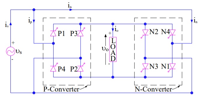
It consists of a total of eight number of thyristors, P1 to P4 i.e. four for positive group and the remaining four N1 to N4 for negative group. Here, positive group doesn’t mean that these SCRs will conduct for positive half cycle of input AC supply rather it means that when (P1 & P2) or (P3 & P4) conducts, the output voltage is positive. Similar is the case with negative group.
It should also be noted that the input and output is single phase AC in the above circuit diagram. Assumed positive direction of voltage and current is marked in the circuit diagram. Load has been assumed resistive.
Single Phase to Single Phase Cycloconverter Working:
The working principle of a single phase to single phase bridge type step-up cycloconverter is based on the switching and commutation of thyristors in a proper sequence. Let us understand this in detail.
In the circuit diagram, during positive half of the input supply voltage “a” is positive with respect to “x”. This makes thyristor pairs (P1 & P2) and (N1 & N2) forward biased from ωt = 0 to ωt = π. The switching and commutation sequence of various thyristors and resulting output voltage is shown in figure below.

When forward biased thyristors (P1 & P2) are turned ON together at ωt = 0, the load voltage is positive with terminal “A” positive with respect to terminal “O”. Load voltage thus traces the positive envelop of the supply voltage.
At ωt1, the conducting thyristors P1 & P2 are force commutated and forward biased thyristor pair N1 & N2 are turned ON. As soon as (N1 & N2) are turned ON, the load voltage becomes negative with terminal “A” negative with respect to terminal “O”. Load voltage, thus, follows the negative envelop of the input supply voltage. Again, at ωt2, the thyristor pairs N1 & N2 are force commutated and forward biased thyristors P1 & P2 are fired to turn it ON. The load voltage is now positive and follows the positive envelop of input supply. Basically, the switching frequency is decided by the required output frequency. The more the required output frequency, the more will be the thyristor switching frequency.
After ωt = π, thyristor pairs (P1 & P2) and (N1 & N2) becomes reversed biased but thyristor pairs (P3 & P4) and (N3 & N4) are forward biased. These forward biased thyristors can be turned ON and force commutated from ωt = π to ωt = 2π. In this way, a high frequency turning ON and force commutation of pairs (P1 & P2), (N1 & N2) and (P3 & P4) and (N3 & N4) gives a high frequency output voltage at the load terminal.
In the above waveform, note that there is a total of 6 cycles of output in one cycle of input supply. This means that frequency of output voltage is 6 times of input frequency i.e. fo = 6fs where fo and fs are output and supply frequency respectively.
maa kasam chumma content hai bhai…all heros do not wear caps.. here, take my bow, king
Thank you brother. Kindly share