Step-up cycloconverter is a single phase to single phase device which converts input AC power at one frequency to output power at a different frequency. The output frequency is more than the input frequency for this cycloconverter. Single phase to single phase means that both the input power and output power are single phase. This article presents the working principle of Step-up Cycloconverter with relevant circuit diagram and waveforms.
Working Principle of Step-up Cycloconverter:
The working principle of a step-up cycloconverter is based on switching of thyristors in a proper sequence. The thyristor acts as a power switch. These switches are arranged is a specific patter so that the output power is available for both the positive and negative half of the input power supply. Forced commutation technique is used to turn OFF the conducting thyristor.
Two circuit configurations are possible for step-up cycloconverter: Mid-point Type and Bridge Type. In this article, we will consider mid-point type of circuit arrangement for better understanding of working principle.
Circuit Diagram:
Figure below shows the circuit diagram of Mid-point step-up cycloconverter:
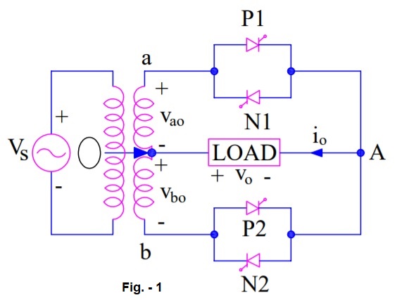
The circuit consists of a single phase transformer with mid tap on the secondary winding and four thyristors. Two of these thyristors P1 & P2 are for positive group. Here positive group means when either P1 or P2 conducts, the load voltage is positive. Other two thyristors N1 & N2 are for negative group. Load is connected between secondary winding mid-point O and terminal A. The load is assumed resistive for simplicity. Assumed positive direction for voltage and current are marked in the circuit diagram.
Operation of Step-up Cycloconverter:
During the positive half cycle of input supply voltage, positive group thyristors P1 & N2 are forward biased for ωt = 0 to ωt = π. As such SCR P1 is fired to turn it ON at ωt = 0 such that load voltage is positive with terminal A positive and O negative. The load voltage, thus, follows the positive envelop of the input supply voltage. At some time instant ωt = ωt1, the conducting thyristor P1 is force commutated and the forward biased thyristor N2 is fired to turn it ON. During the period N2 conducts, the load voltage is negative because O is positive & A is negative this time. The load or output voltage traces the negative envelop of the supply voltage. This is shown in figure below.
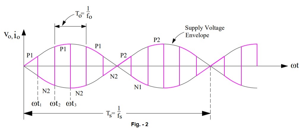
At ωt = ωt2, N2 is force commutated and P1 is turned ON. The load voltage is now positive and follows the positive envelop of the supply voltage. At ωt = π, terminal “b” is positive with respect to terminal “a”; both SCRs P2 & N1 are therefore forward biased from ωt = π to ωt = 2π. AT ωt = π, N2 is force commuated and forward biased SCR P2 is turned ON. The load voltage is positive and follows the positive envelop of supply voltage.
If the supply frequency is fs and output frequency is fo, P2 will be force commutated at ωt = (1/2fs) + (1/2fo). Carefully note this from the waveform shown in the figure-2.
When P2 is force commutated, forward biased SCR N1 is turned ON. This time, the load voltage is negative and follows the negative envelop of the supply input.
In this manner, SCRs P1, N2 for the first half cycle; P2, N1 in the second half cycle and so on are switched alternately between positive and negative envelops at a high frequency. This results in output frequency fo more than the input supply frequency fs. In our example of figure-2, note that there is a total of 6 cycles of output in one cycle of input supply. This means that frequency of output voltage is 6 times of input frequency i.e. fo = 6fs.