Start Delta Starter is a scheme for motor starting to reduce the inrush current during starting of the motor. This method of starting is quite popular for Delta connected Squirrel Cage induction motor. In this method, the motor is first started as a star connected motor and as soon as the motor reaches near to or rated speed, it is run as Delta connected motor. In this post, we will be discussing the requirement, working principle and disadvantage of Star Delta Starter.
Requirement of Star Delta Starter
As we know that when a 3 phase induction motor is started at its rated voltage, it draws high inrush current whose magnitude is around 5 to 7 times of the rated motor current. This means, if the rated current of a motor is 20 A then during starting it will take around 100 to 140 A. This high value of starting current may result in considerable voltage dip of the supply line feeding the motor. Due to this voltage dip, the other equipment connected to the supply may get effected. In order to limit this starting current to some reasonable value, some methods are adopted to start three phase induction motor. Star Delta Starter is one among the various starting methods.
Working Principle of Star Delta Starter
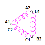
As discussed earlier, star delta starter automatically changes the motor winding configuration from STAR (during starting) to DELTA (when the motor reaches its rated speed). This itself means that all the six winding terminal of motor must be taken out and connected to the starter. The winding terminals corresponding to R, Y & B phases are generally designated as (A1, A2), (B1, B2) and (C1, C2) respectively. Sometime it is also marked as (U1, U2) for R phase, (V1, V2) for Y phase and (W1, W2) for B phase. This nomenclature can easily be seen in the motor terminal box.
Schematic diagram of star delta starter is shown below.
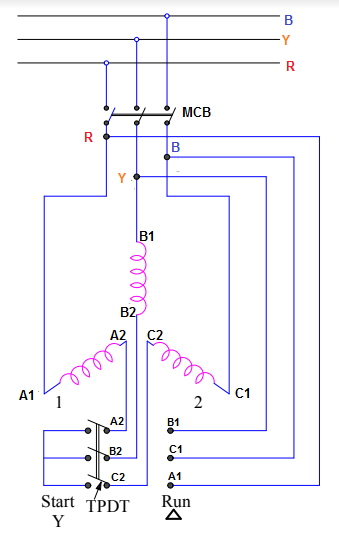
Star delta starter consists of a power MCB and Three Pole Double Throw (TPDT) Switch. This TPDT switch has two positions: Start and Run. Let us now consider two cases to better understand the functioning of this starter.
Case-1: TPDT Switch is at “Start” Position and MCB is ON.
Under this assumed condition, motor winding terminals A2, B2 and C2 are shorted by the switch as can be seen in the schematic diagram. Thus the motor winding STAR point is formed by the Switch while the other winding terminals A1, B1 and C1 are connected to R, Y & B phase of power supply through MCB. Thus the motor is now STAR connected, fed through the power supply when TPDT switch is at Start position. You might think what we are achieving by making motor STAR connected during starting? The straight forward answer is to limit the magnitude of starting current. But ,how?
If VL be the line voltage and Z be the standstill per phase leakage impedance, then per phase starting current (I1) flowing through the motor will be given as below.
I1 = Starting current when motor is STAR connected
= Phase Voltage / Standstill per Phase Leakage Impedance
= (VL / √3Z)
Since motor is STAR connected, hence phase and line currents will be same.
Therefore line current
= (VL / √3Z).
Now suppose, instead of using star delta starter, we are directly feeding the DELAT connected motor through supply which is the case in DOL (Direct On Line) starting. In this case, the per phase motor starting current (I2) will be
I2 = (VL / Z)
Since motor is DELTA connected, therefore line current will be equal to the √3 times the phase current.
Line current in DOL starting
= √3(VL / Z)
Ration of Line current in Start Delta Starting and DOL starting
= (VL / √3Z) / [√3(VL / Z)]
= 1/3
Thus we see that, the starting line current for DELTA connected motor has reduced to (1/3) times of what it would have been for DOL starting. This is the reason we go for star delta starter.
Case-2: TPDT Switch is at “Run” Position and MCB is ON.
When TPDT switch is put at Run position, the winding terminals (A2, B1), (B2, C1) & (C2, A1) are connected together as shown in schematic diagram. This changeover in winding connection leads to DELTA connected motor.
Generally this changeover from Start to “Run” position takes place when the speed of motor reaches near to or equal to rated speed. This change in winding configuration is automatic through the use of timer and doesn’t require manual intervention. A control scheme is implanted to make the process of automatic and smooth.
Disadvantage of Star Delta Starter
The major disadvantage of star delta starter is reduced starting torque. This is due to starting of motor at reduced voltage using the starter.
As we know that torque in an induction motor is directly proportional to square of applied voltage. The applied voltage for star delta starter is (VL / √3). Therefore,
Starting Torque = k (VL2 / 3)
where k is constant of proportionality.
Applied voltage in case of DOL starting of DELTA connected motor is line voltage i.e. VL. Therefore,
Starting Torque = kVL2
Thus the ratio of starting torque of DELTA connected motor during star delta and DOL starting
= 1/3
From the above ratio, we see that the starting torque for Star Delta Starter has become (1/3)rd of that would have been for DOL starting. This is the disadvantage. However, Star Delta Starter is cheap as compared to other starting methods and hence used extensively. It is used mainly for the application for which starting torque requirement is less than or equal to 50% of rated torque.
Nice article
Amazing article!
Content is good but a bit confusing i guess and There is a typing error in first pera 4th line
Thank you!corrected.Could you please expalin where the confusion is arising? We will make that vivid.
starting torque is proportional to the square of line voltage for both star and delta connections but you took applied voltage as (Vl/root 3). Did I miss anything here?