This article outlines the definition, working principle and derivation & formula for average output voltage of a Step-down Chopper. The working principle has been discussed in detail with the help of circuit diagram & output voltage waveform.
Definition:
A Step-down chopper is a static device that step downs its DC input voltage. The value of average output DC voltage of this chopper is less than that of its fixed DC input source voltage. This type of chopper is more common.
Working Principle:
Before we start discussing the working principle of Step-down Chopper, it is imperative to first have a look at its circuit diagram. The circuit diagram is shown in figure below.
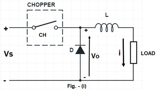
The chopper is shown within a dotted line and assumed to be a switch. This circuit consists of inductor L, a free-wheeling diode, chopper CH, Source and Load. Fixed DC input voltage Vs is applied and our aim is to get the variable DC output voltage which is a function of chopper. To get the variable DC voltage, we will switch ON and OFF the chopper CH at some frequency called the chopping frequency (f).
Case-1: When Chopper CH is switched ON.
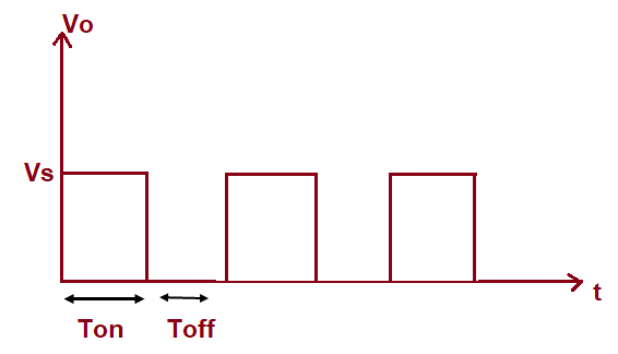
When CH is switched ON, the source is directly connected to load and hence the output voltage Vo becomes equal to Vs. The time period for which chopper is kept ON is called ON Time of chopper and represented by TON. Thus, Vo will be equal to Vs for time TON. The waveform of output voltage and time is shown in figure below.
During the ON period of chopper, the current will build in the load exponentially and will reach its maximum value at the end of TON (It is assumed that TON is less than the time required for load current to reach its steady state value). This, simply means that the maximum value of load current io will be less than the steady state value. The waveform of load current and time of step-down chopper is shown in figure below.
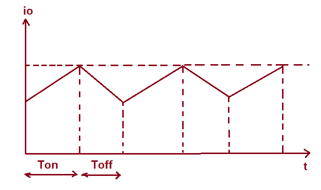
In the above figure, the load current during TON time is shown linearly increasing with time. This is because the chopping frequency is high and hence TON is very less. For a small time period, the exponential rise of current may be approximated to the linear rise.
What about the free-wheeling diode? Free-wheeling diode (D) is reversed biased during TON, hence it doesn’t come into circuit during this period.
Case-2: When Chopper CH is switched OFF.
When chopper in figure-(i) is switched OFF, the load is disconnected from the source Vs and hence load voltage Vo will be ZERO during the entire period for with CH is OFF. The time for which chopper is kept OFF is known as OFF time and represented by TOFF. You may refer the waveform of Vo w.r.t time shown earlier in the post. What about load current io during the TOFF? Will it become zero just like output voltage?
As soon as the CH is switched OFF, the current through the inductor L (io) cannot suddenly drop to zero. Rather, it starts decreasing and hence the polarity of induced emf across the inductor reverses (opposite of polarity as shown in figure-i).
This induced emf of inductor makes free-wheeling diode forward biased and hence, free-wheeling diode (D) acts as a short during TOFF. Thus, the load current continues to decay through inductor L, free-wheeling diode D and load even though the source Vs is disconnected. Kindly refer the waveform of load current w.r.t time shown earlier. The load current reaches its minimum value during OFF time and then CH is again switched ON. Therefore, case-1 and case-2 repeats.
Derivation of Average Output DC Voltage:
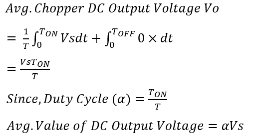
To find the average output DC voltage, carefully observe the Vo vs. time waveform shown earlier in the post. What you observe? You will notice that Vo is equal to Vs for TON time and is ZERO for TOFF time. As we know that average value of any periodic function f(x) with time period T is given as below.
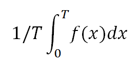
Therefore, using the above formula we can easily find the value of average value of output voltage of Step-down chopper. It should be noted that the time period of chopper DC Output Voltage Waveform is T = TON + TOFF. The derivation of output voltage of chopper is shown below.
Formula of Average DC Output Voltage:
The formula for Average DC Output Voltage of step-down chopper is shown below.
From the above formula, it can be concluded that the output voltage of step-down chopper can be varied from zero to source voltage Vs. This is achieved by varying the duty cycle (α).