Definition:
Step-up chopper is a static device whose average output DC voltage is greater than its input DC voltage. It is different from the step-down chopper. In step-down chopper, the average value of output voltage stepped down i.e. it is less than its input voltage.
Working Principle of Step-up Chopper:
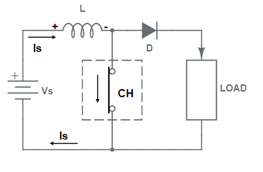
To understand the working principle, let us first have a look at the circuit diagram of step-up chopper. This is shown in figure below. In the circuit diagram, chopper is shown as a switch CH. We will understand the working of this chopper in two steps: Switch ON period and Switch OFF period of chopper.

Switch ON Period: When chopper (CH) is switched ON, the current will flow through the closed path formed by supply source Vs, inductor L and chopper CH. During this period, no current will flow through the load. Only source current is will flow and the value of load current io will be ZERO during the ON period. This case is depicted in figure below.
Also, during the TON period, energy is stored in the inductor L. This energy storage in L is essential to boost the load output voltage above the source voltage. Therefore, a large value of L is essential in a step-up chopper.
Switch OFF period: When the chopper CH is switched OFF, the current through the L can not die instantaneously rather it decays exponentially. Due to this behavior of L, it will force the current through the diode D and load for the entire time period TOFF. This is shown in figure below.

Since, the current through the inductor L tends to decrease, the polarity of the emf induced in inductor L is reversed as shown in above figure. As a result, the voltage across the load becomes equal to the sum of source voltage and emf induced in inductor. Thus, the output voltage exceeds the source voltage Vs. The load / output voltage may be written as below.
Vo = Vs + L(di/dt)
Thus, the circuit works as a step-up chopper. It may be noted here that, the voltage across the load increases because the inductor releases its stored energy to the load during the OFF period.
Analysis of Waveform:
Various waveform i.e. source voltage, source current, load voltage and load current waveform are shown in figure below.
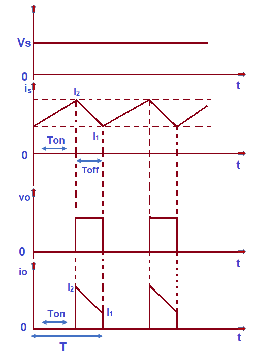
The first waveform represents the source voltage which is a DC voltage equal to Vs. Therefore, it is shown as a straight line parallel to time axis. Second waveform shows the source current is. When chopper (CH) is switched ON, the source current increases from its minimum value I1 to maximum value I2. It may also be noted that, this source current flows through the inductor during ON time. Therefore, it may be said that the current through the inductor L rises from I1 to I2 during ON period. During this time, no current flows through the load as shown in io versus time (t) graph.
When chopper is switched OFF, the source current starts decreasing from its peak value I2 to least value I1. Thus, the current through the inductor decreases from I2 to I1 during the OFF period. Since, load only comes into circuit during the OFF period, it may be said that, load current decreases from I2 to I1 during OFF time.
Calculation of Output Voltage:
Let us now find the expression for the output voltage of step-up chopper. From the above analysis of source current and load current waveform, it is clear that, the average value of current flowing through load and inductor are same and equal to (I1+I2)/2.
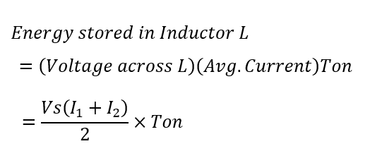
As discussed earlier in the article, the energy is stored in L during chopper ON time. This stored energy in L during the ON period is equal to the multiplication of voltage across the inductor, average current through it and TON time. The voltage drop across L during ON time equal to the source voltage Vs. This is evident from the circuit diagram.
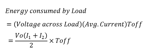
When chopper is switched OFF, this stored energy is transferred to the load. Let the load voltage (output voltage) be Vo. Since, the average current through load is (I1+I2)/2, therefore, the energy consumed by load during this OFF time of chopper is given as below.
This energy consumed by load is supplied by source (Vs) and the inductor L. The energy supplied by source to load will be equal to multiplication of source voltage Vs, average current (I1+I2)/2 and TOFF time.

From the above formula for output voltage of step-up chopper, it can be seen that output voltage can be stepped up by varying the duty cycle α. If the chopper is always OFF, α = 0 and hence, the output voltage Vo will be equal to source voltage Vs. Similarly, if chopper is kept always ON, the value of duty cycle will become unity and hence output voltage will become infinite. However, chopper is turned ON and OFF in such a manner that duty cycle is variable and the required stepped up average output voltage, more than source voltage, is obtained.
your website is very helpful for us and we hope you will provide contents like this .
Thank you! Kindly share the articles as it motivates us.