What is Differential Protection?
Differential Protection is based on the fact that any fault within electrical equipment will result into the difference in current entering it and the current leaving it. Thus by comparing the two currents either in magnitude or in phase or both we can determine a fault and issue a trip decision if the difference exceeds a predetermined set value. The difference in current is called the differential current.
Principle of Differential Protection:
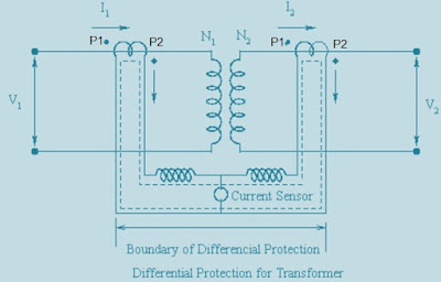
In this post we will discuss about the Differential Protection of a Transformer. Consider an ideal transformer with the CT connections, as shown in figure below.
Suppose that current rating of primary winding = 100A
Current rating of secondary winding = 1000A.
Then if we use 100/5 and 1000/5 CT on the primary and secondary winding respectively, then under normal operating conditions the both CT currents will be 5 A in magnitudes.
By connections the primary and secondary CTs with due care to the dots (In actual CT polarity marking is by Terminal P1 and P2. Current is supposed to flow from P1 to P2), a circulating current can be set up as shown by dotted line.
No current will flow through the branch having overcurrent current relay in normal condition as
Differential current Id = 5-5 = 0 A
Now if an internal fault occurs within the Transformer like interturn short etc., then the normal mmf balance is upset i.e. under this condition, the CT secondary currents of primary and secondary side CTs will not match. The resulting differential current will flow through overcurrent relay. If the pickup setting of overcurrent relay is close to zero, it will immediately pick up and initiate the trip decision.
In practice, the transformer is not ideal. A differential current always flows through the overcurrent relay. Therefore overcurrent relay pick up is adjusted above the no load current value.
In Differential Protection of Transformer CT matching is an important thing to care care else differential protection won’t be efficient and reliable.
Let the transformer turns ratio is N1/N2 and the current in primary & secondary of transformer are I1 and I2 respectively. Suppose CT-1 having ratio of 1/n1 is installed in primary whereas CT-2 having ratio of 1/n2 is installed in secondary.
Therefore,
Current in CT – 1 primary = I1
Current in CT – 1 secondary =I1/n1
Current in CT – 2 primary = N1I1/N2
Current in CT – 2 secondary = N1I1/N2n2
In normal operating condition of Transformer, the differential current through the Relay should be zero. Therefore,
Current in CT – 1 secondary = Current in CT – 2 secondary
I1/n1= N1I1/N2n2
N2n2 = N1n1
Thus CT should be selected in such a way that their Turn Ratio satisfies
N2n2= N1n1
In case, Transformer Tap is used then nominal Tap position should also be taken into account.
When dealing with three phase transformers, the transformer connections like Y-Y or delta – delta connection play a great role in determining CT secondary interconnections to establish circulating current scheme. This is because of the phase shifts typically of the order of +- 30° that result in the line currents when we move from primary to secondary side of the power transformer. If transformer winding are connected in Y configuration then use DELTA configuration for corresponding CT secondary interconnections and vice-versa. “
Thank you!

Hi there
I am testing Engineer, working @ABB-KSA. This web site is very useful and the the topics are essentially important, great deal of thanks for such amazing information.
Thank you very much! Please share if you like it.
Let the transformer turns ratio given N1/N2 and the corresponding CT ratio be given by 1/n1 and as 1/n2.
Therefore,
Current in CT – 1 primary = I1
Current in CT – 1 secondary =I1/n1
Current in CT – 2 primary = N1I1/N2
Current in CT – 2 secondary = N1I1/N2n2
In normal operating condition of Transformer, the differential current through the Relay should be zero. Therefore,
Current in CT – 1 secondary = Current in CT – 2 secondary
I1/n1= N1I1/N2n2
N2n2 = N1n1…….sir I can’t understand these things kindly give explanation sir
Please check now. If you still have doubt, please comment.
Sir, up to my knowledge, in Y-Y or delta-delta 3 phase transformer, the current in both primary and secondary will not have any phasor difference, rather phasor difference of +-30 can be seen in Y-delta or delta-Y star transformer. Kindly clarify for the same and correct me if I am wrong ASAP!
Yes,phase shift is observed in star delta or delta star transformer.
In delta/delta transformer REF protection applicable or not
REF can be used if there is neutral point. In delta/delta, there is no neutral point and hence can not be used.