Class-D or Type-D chopper is a circuit configuration of chopper in which power can flow in either direction i.e. from source to load and load to source. The operation of this chopper is confined in first and fourth quadrant. This type of chopper is also known as Two quadrant Type-B Chopper. The necessary condition for this chopper is that load should be inductive. This article outlines the working principle / operation of Class-D chopper with circuit diagram and relevant waveforms.
Working / Operation of Class-D Chopper:
To understand the operation / working principle of Type-D chopper, let us first have a look at its circuit diagram shown below.

In this circuit, CH1 and CH2 represents two choppers which can be made ON / OFF. We shall consider two cases for explaining the operation.
Case-1: CH1 and CH2 both are switched ON simultaneously.
When both the choppers are switched ON, the load is directly connected to source and hence the output voltage Vo will become equal to the source voltage Vs. The current flows from source to load in this case. Thus, both the current and output voltage i.e. io and vo are positive in this case, hence the operation is in first quadrant.
It should be noted that diode D1 and D2 are reversed biased in this case and hence they can be treated as an open switch.
Case-2: CH1 and CH2 both are switched OFF simultaneously.
When both the choppers are made OFF simultaneously, the current through the load doesn’t suddenly drops to zero due to inductive nature of load. However, it decays gradually and hence a huge amount of voltage is induced in the inductor in the reverse direction (opposite to the direction of vo). This makes diode D1 and D2 forward biased. Thus, D1 and D2 starts conducting and connects the load to source again. But this time, the current flows from load to source (carefully observe the circuit diagram). It shall be noted that, the direction of load current has not changed. The current is still flowing as shown by the direction of io in the diagram but the polarity of vo has changed. Thus, io is positive but vo is negative and hence operation of chopper is in fourth quadrant. The power flows from load to source.
The first and fourth quadrant operation of class-D / Type-D chopper is shown by the hatched area in the figure below.

Various Waveforms:
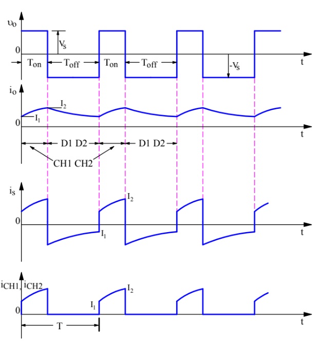
Now, we will discuss the various waveform of class-D or Type-D chopper. Figure below represents various waveforms during the time both the chopper are ON.

During the ON time of CH1 & CH2, output voltage vo is positive and equal to vs (recall Case-1). When both the choppers are made OFF, the output voltage reverses and hence becomes negative (recall Case-2).
It may be noticed that, the average value of output voltage vo may either be positive or negative. It depends on TON and TOFF time. If TON time is more than TOFF time then positive part of vo Vs. t graph will be more than the negative part and hence average value will be positive.
If TOFF is more than the TON time, the negative part of vo Vs. t graph will be more than the positive part and hence average value of output voltage will be negative. This is depicted in the waveform shown below.
Thus, the average output voltage of Class-D chopper may either be positive or negative depending upon whether TON is more or TOFF.
Average output voltage Vo is given as below.
Vo = Vs [(TON – TOFF) / T]
where T = TON+TOFF
From the above formula, following points can be concluded and the same can be checked from quadrant operation of class-D chopper shown earlier in the figure:
- In case TON>TOFF i.e. duty cycle α>0.5, Vo is positive.
- In case TON<TOFF i.e. duty cycle α<0.5, Vo is negative.
- In case of TON = TOFF, α = 0 and hence, Vo = 0.
Now, refer the waveform of load current. It can be seen that; load current is always positive irrespective of CH1 & CH2 are ON or OFF. Thus, the average value of load current Io will always be positive.
You may also refer waveform of source current is and chopper current iCH1 or iCH2. It may be noticed from source current is waveform that it is negative when both CH1 and CH2 are OFF. It may also be said that is is negative when diode D1 and D2 conducts. Negative source current means, current is flowing into the source as discussed in Case-2. Kindly write in comment box if in doubt or for feedback. Thank you!