A four quadrant chopper is a chopper which can operated in all the four quadrants. The power can flow either from source to load or load to source in this chopper. In first quadrant, a Class-E chopper acts as a Step-down chopper whereas in second quadrant it behaves as a Step-up chopper. This type of chopper is also known as Class-E or Type-E chopper. This article describes the working principle and operation of Class-E chopper with the help of circuit diagram.
Working Principle / Operation of Class-E Chopper:
The circuit of a four quadrant chopper or class-E chopper basically consists of four semiconductor switches CH1 to CH4 and four diodes D1 to D4. The four diodes are connected in anti-parallel. The circuit diagram of this type of chopper is shown below.
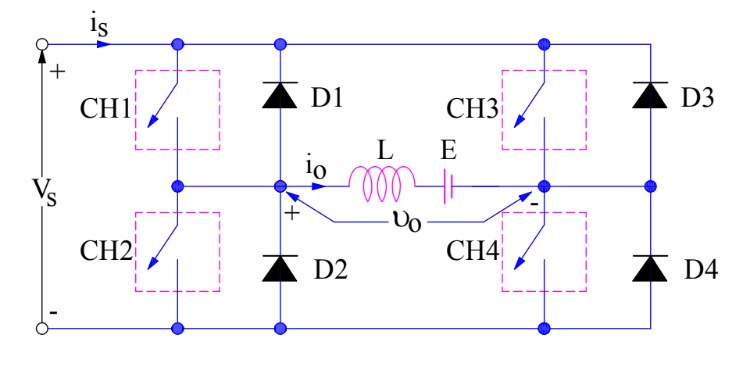
In the above circuit diagram, the choppers are numbered CH1 to CH4. For first quadrant operation CH1 is made ON, for second quadrant operation CH2 is made ON and so on. To better understand the working of four quadrant chopper, we will discuss its operation separately for each quadrant.
First Quadrant Operation:
For first quadrant operation, CH4 is kept ON, CH3 is kept OFF and CH1 is operated. When both CH1 & CH4 are ON simultaneously, the load gets directly connected to the source and hence the output voltage becomes equal to the source voltage. This essentially means that vo = vs. It may be noted that the load current flows from source to load as shown by the direction of io.
When CH1 is switched OFF, the load current free wheels through CH4 and D2. During this period, the load voltage and current remains positive.
Thus, both the output voltage vs and load current io are positive and hence, the operation of chopper is in first quadrant. It may be noted that, Class-E chopper operates as a step-down chopper in this case.
Second Quadrant Operation:
To obtain second quadrant operation, CH2 is operated while keeping the CH1, CH3 & CH4 OFF. When CH2 is ON, the DC source in the load drives current through CH2, D4, E and L. Inductor L stores energy during the On period of CH2.
When CH2 is turned OFF, current is fed back to the source through D1, D4. It should be noted at this point that (E+Ldi/dt) is more than the source voltage Vs. As load voltage Vo is positive and Io is negative, it is second quadrant operation of chopper. Since, the current is fed back to the source, this simply means that load is transferring power to the source. Kindly read Step-up chopper for detailed analysis and better understanding.
For second quadrant operation, load must contain emf E as shown in the circuit diagram. In second quadrant, configuration operates as a step-up chopper.
Third Quadrant Operation:
To obtain third quadrant operation, both the load voltage and load current should be negative. The current and voltage are assumed positive if their direction matches with what shown in the circuit diagram. If the direction is opposite to what shown in the circuit diagram, it is considered negative. One important thing to notice is that the polarity of emf E in load must be reversed to have third quadrant operation. Circuit diagram of Class-E chopper for third quadrant operation is shown below.

For third quadrant operation, CH1 is kept off, CH2 is kept ON and CH3 is operated. When CH3 is ON, load gets connected to source and hence load voltage is equal to source voltage. But carefully observe that the polarity of load voltage vo is opposite to what shown in the circuit diagram. Hence, vo is assumed negative. Let us now see what is the status of load current io. It may be seen that io is flowing in the direction opposite to shown in the circuit diagram and hence negative.
Now, when CH3 is turned OFF, the negative load current free wheels through the CH2 and D4. In this manner, vo and io both are negative. Hence, the chopper operates in third quadrant.
Fourth Quadrant Operation:
To obtain fourth quadrant operation, CH4 is operated while keeping CH1, CH2 and CH3 OFF. The polarity of load emf E needs to be reversed in this case too like third quadrant operation.
When CH4 is turned ON, positive current flows through CH4, D2, L and E. Inductance L stores energy during the time CH4 is ON. When CH4 is made OFF, current is fed back to the source through diodes D2, D3. Here load voltage is negative but the load current is always positive. This leads to chopper operation in fourth quadrant. Here, power is fed back to the source from load and chopper acts as a step-up chopper.
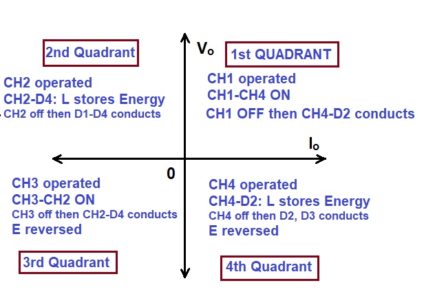
The operation of a four quadrant chopper or Class-E chopper is summarized in the figure below.
Can the drive be operated in 4th quadrant, for a positive armature voltage… are there any such conditions ?