Synchronous Machine is electromechanical equipment in which the speed of rotating part i.e., Rotor, is equal to the speed of rotation of magnetic flux. The speed of rotation of magnetic flux is called synchronous speed. That is why these types of equipment is called synchronous machine. This article outlines the constructional detail and type of synchronous machine.
Construction of Synchronous Machine
Synchronous Motor and Synchronous Generator are together refereed as Synchronous machine. Their basic construction is also same. Therefore, construction of synchronous machines discussed in the post applies well for synchronous motor and generator.
From construction point of view, a synchronous machine consists of two main parts: Stationary part known as Stator and Rotating part known as Rotor.
Stator
Stator is the outer stationary part of the machine which consists of two main parts:
Yoke – This is outer cylindrical stationary frame and made up of either cast steel or cast iron.
Stator Core – It is the magnetic core which is slotted to accommodate armature winding. It comprises of set of slotted steel laminations pressed into the cylindrical space inside the outer frame. Stator core is made of laminated sheet of 0.5 mm thick CRGO to reduce eddy current losses. Refer the figure below for better understanding and insight into the construction of synchronous machine.
Figure below depicts the stator of synchronous generator. Carefully observe the stator core embedded armature conductor in the slots.
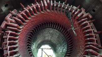
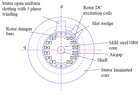
Set of insulated windings are placed inside the slot of stator core as shown in figure above. In case of three phase generators, three sets of windings are required, one for each phase connected in star. The cross-sectional area of these windings must be enough to carry rated current of the machine. Figure below illustrate the simplified construction of synchronous machine.
In case of Synchronous Generators, it is not possible to punch all the laminations in cylindrical form. Therefore, laminations are stacked in segments. A number of segments are assembled together to form cylindrical stator core. Stacking of segments to make cylindrical core of synchronous generator is shown in figure below:

All the segments are insulated from each other by thin layer of varnish.
Rotor
Rotor is that part of synchronous machine which can rotate. It carries the field winding. From construction point of view, there are two types of rotor: Salient Pole Rotor and Cylindrical Pole Rotor. Cylindrical pole rotor is also known as round rotor or non-salient pole rotor. To know the difference between the Cylindrical Pole and Salient Pole Rotor, please read Difference between Cylindrical and Salient Pole Rotor.
Hydro-generator rotors are salient pole type. It is made of silicon steel lamination of 0.5 to 0.8 mm thickness to reduce eddy current losses and hence heating. The field winding or DC winding are concentrically wound on the salient pole rotor. This type is only suitable for low speed machine. It is not favorable for high speed machine as due to high centrifugal force on the salient pole, the pole faces may damage. The basic construction of rotor of synchronous machine is shown below.

In case of turbo alternator the rotors are manufactured form solid steel forging. The rotor is slotted to accommodate the field winding. Normally two third of the rotor periphery is slotted to accommodate the winding and the remaining one third unslotted portion acts as the pole. Rectangular slots with tapering teeth are milled in the rotor. Generally rectangular aluminum or copper strips are employed for filed windings. To get feel of rotor manufacturing by solid steel forging, refer the figure below. Figure below shows the rotor construction.

The field windings and the overhangs of the field windings are secured in place by steel retaining rings to protect against high centrifugal forces. Hard composition insulation materials are used in the slots which can withstand high forces, stresses and temperatures.

Damper windings are provided in the pole faces of salient pole alternators. Damper windings are the copper or aluminium bars housed in the slots of the pole faces. The ends of the damper bars are short circuited at the ends by short circuiting rings similar to end rings as in the case of squirrel cage rotors. These damper windings provide mechanical balance and damping effect. It also reduces the effect of over-voltages and damp out hunting in case of synchronous generator. In case of synchronous motors, damper winding act as rotor bars and help in self starting of the motor.
Types of Synchronous Machine
Based on the armature winding and field winding arrangement, synchronous machines are classified into two types: Rotating Armature type and Rotating Field type.
- In rotating armature type, the armature winding is housed in the rotor. The emf generated or current is supplied to the load via slip ring and carbon brush assembly. This type of synchronous machine is only built for small rating machine.
- In rotating field type synchronous machine, filed winding is wound on the rotor. DC supply is extended to the field winding by assembly of slip ring and carbon brush. Electrical power is supplied to the load using stationary terminals mounted on the stator. This type is more famous and widely used in large sized synchronous machine.
On the basis of type of prime mover, synchronous generators are classified as:
- Hydro-generators: The generators which are driven through hydro-turbine is called hydro-generator. These are basically salient pole type and run at a slower speed of the order of 1000 rpm or lower.
- Turbo-generators: These generators are driven through steam turbine and convert thermal energy of steam into electrical energy. These are cylindrical pole rotor type and runs at higher speed. Normally the speed of rotor is governed by the frequency of Grid. If the frequency of Grid is 50 Hz, the speed of two pole generator rotor is 3000 rpm (Ns = 120×50 / 2 = 3000).
- Engine driven Generators: These generators are driven by IC engine and their speed is lower than 1500 rpm.