This article outlines the Circuit Diagram, Working Principle, Various waveforms, Advantages and Disadvantages of Load Commutated Chopper.
Circuit Diagram of Load Commutated Chopper:
Load Commutated Chopper is a type of chopper which consists of four thyristors and one commutating capacitor. Figure below shows the circuit diagram of a load commutated chopper. Four thyristors are shown as T1-T4 and C is the commutating capacitor.
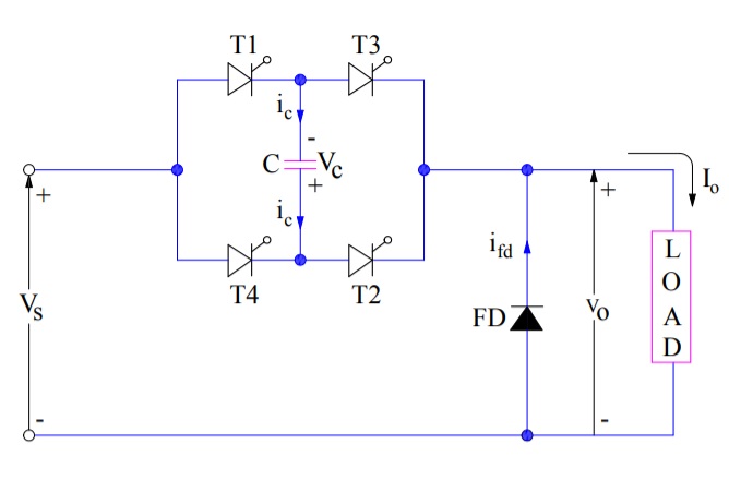
The thyristors T1 & T2 acts together as one pair and thyristors T3 & T4 acts together as second pair for conducting the load current alternatively. When T1 & T2 are conducting, these acts as main thyristors while T3, T4 and C acts as commutating components. Similarly, when T3 & T4 acts as main thyristors, T1, T2 and C acts as commutating components. Free-wheeling diode FD is connected across the load to conduct the load current when required.
Initially the capacitor C is charged to a voltage Vs with upper plated negative and lower plate positive as shown in the circuit diagram. To make the analysis simple, following assumptions are made:
- Load current is constant
- SCRs and diodes are ideal switch
Working Principle of Load Commutated Chopper:
The working principle of load commutated chopper can be explained in three different modes as described below:
Mode-I:
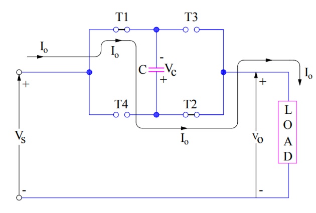
With the capacitor C charged with upper plate negative and lower plate positive, the load commutated chopper is ready for its operation. When thyristor pairs T1 & T2 are triggered at t=0, the load current flows through T1, C and T2. As the load current is assumed constant, the upper plate of capacitor will start charging from negative to positive. The output voltage Vo for this mode is given as below:
Vo = Vs+Vc
Since, the capacitor voltage is -Vs at t=0, the output voltage will shoot up to 2Vs at as soon as the thyristors T1 and T2 are triggered. Mode-I operation of load commutated chopper is shown in figure below.
The capacitor C is charged linearly (as load current is constant, hence capacitor charging will be linear) from Vs at t=0 to (-Vs) at t=t1. When capacitor voltage becomes -Vs (this essentially means that upper plate is positive and lower plate is negative), the load voltage falls rom 2Vs to zero at t = t1. Kindly refer the waveform of output voltage and time for corelating the things.
It should be noted that when T1 & T2 are triggered, T3 and T4 are reversed biased due to capacitor voltage. However, at the end of Mode-I i.e. t=t1, these thyristors become forward biased.
Mode-II:
At t=t1, the capacitor C gets slightly overcharged, as a result free-wheeling diode gets forward biased and hence, load current is transferred from T1 & T2 to FD. From t=t1 onwards, load current free-wheels through FD. This mode of operation is shown in figure below.
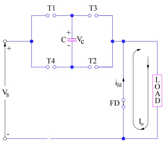
During this mode, the output voltage Vo is zero as load current is circulating through the free-wheeling diode. The voltage across capacitor remains fixed to that at the end of mode-I i.e. (-Vs). This mode of operation continues until thyristors T3 & T4 are triggered. Let us assume that Mode-II operation continues till t=t2. This means that at t=t2, thyristors T3 & T4 are triggered at t=t2 and Mode-III operating begins.
Mode-III:
At t=t2, thyristor pair T3 & T4 are triggered. Load current flows from source to load through T3, T4 and capacitor C. This mode of operation is shown in the figure below.
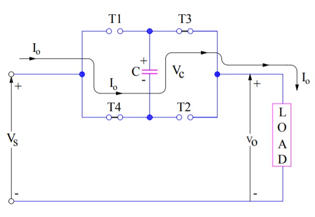
Since load voltage is given as
Vo = Vs+Vc
As soon as T3 & T4 are triggered, the load voltage becomes equal to 2Vs. Thyristor pairs T1 & T2 are reversed biased due to capacitor voltage and hence turned off at t=t2. Since the load current (Io) is flowing through the capacitor, it will charge the capacitor linearly from (-Vs) at t = t2 to Vs at t = t3. At t=t3, the capacitor voltage becomes equal to Vs and hence the load voltage falls from 2Vs to zero at t3. Mind that, when capacitor voltage becomes Vs (this means upper plate negative and lower plate positive), thyristor pairs T1 & T2 gets forward biased at t3.
At t3, capacitor C is somewhat overcharged and hence load current circulates through free-wheeling diode FD. When T1 & T2 are turned ON at t4, mode-I repeats.
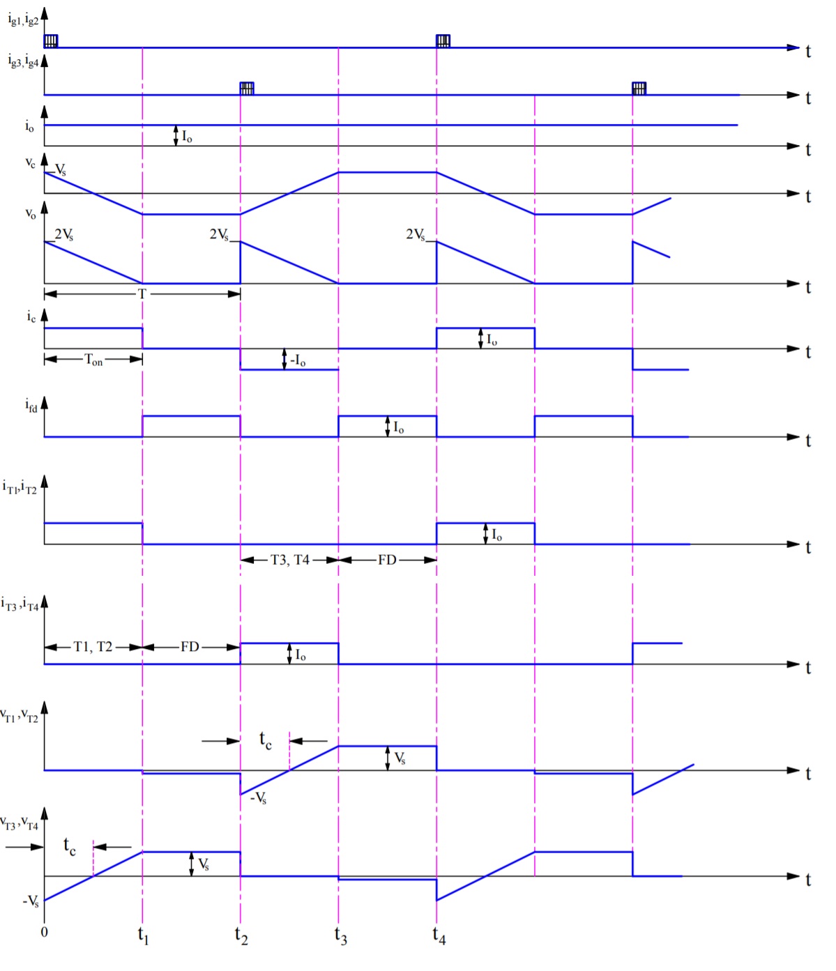
Related Waveforms:
Various waveforms related to load commutated chopper is shown in figure below.
Advantages & Disadvantages of Load Commutated Chopper:
Advantages:
Following are the major advantages of load commutated chopper:
- It is capable of commutating any amount of load current.
- No inductor is required for commutation. Generally, inductor is bulky, costly and nosier.
- Filtering requirement is minimum in load commutated chopper as it can work at high frequencies in the order of kHz.
Disadvantages:
Following are the major disadvantages of load commutated chopper:
- The peak voltage in this chopper is twice the source voltage. This peak can however be reduced by filtering.
- The efficiency of this chopper is low for high power applications because of higher switching losses at high frequencies.
- Free-wheeling diode is subjected to twice the supply voltage.
- The commutating capacitor has to carry the full load current at a frequency of half the chopping frequency.