Single Phase AC Voltage Controller is a device which converts fixed single phase alternating voltage directly to a variable alternating voltage without a change in frequency. The input and output of the device is single phase.
There are two types of single phase AC Voltage Controller: Single phase Half Wave and Single phase Full Wave. In this article, we will discuss both type of voltage controller in detail and illustrate the working with relevant circuit diagram and waveforms.
Working Principle of Single Phase AC Voltage Controller:
The working principle of any voltage controller is based on sequence of switching operation of some power switches viz. thyristors. The thyristors are so switched on that load gets connected to AC source for a part of each half cycle of input voltage. Thus, the output voltage follows the part of input AC voltage for which the load is connected to source. In this way, the output voltage is controlled.
Let us consider single phase half wave & full wave AC voltage controller for understanding the working principle.
Single Phase Half Wave AC Voltage Controller:
A single phase half wave AC voltage controller comprises of a thyristor connected in anti-parallel with a power diode. The circuit diagram is shown in figure below.
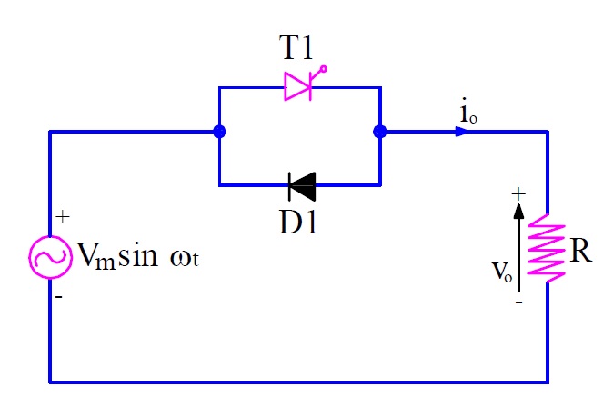
The load is assumed resistive for the sake of simplicity. The input source is VmSinωt.
For the positive half cycle of input source, thyristor T1 is forward biased and hence it is able to conduct provided gate signal is applied. This means that T1 will remain OFF until gate signal is applied. Now suppose, at some angle α (called the firing angle), thyristor T1 is gated. As soon as T1 is fired / gated, it starts conducting and hence, load gets directly connected to the source. This makes load voltage Vo = VmSinα and load current Io = (VmSinα / R) at the instant T1 is fired. From ωt = α to π, the load voltage and current follows the input voltage waveform VmSinωt and (VmSinωt / R) respectively.
After ωt = π, thyristor T1 becomes reversed biased and the load current becomes zero (note that load voltage and current are in phase, hence as soon as load voltage becomes zero, load current also becomes zero) and hence thyristor T1 is commutated naturally.
After ωt = π, diode D1 becomes forward biased and hence starts conducting. This makes load voltage & current to follow the supply voltage VmSinωt and (VmSinωt / R) respectively for the negative half cycle.
The output waveform for load voltage & current is shown below.
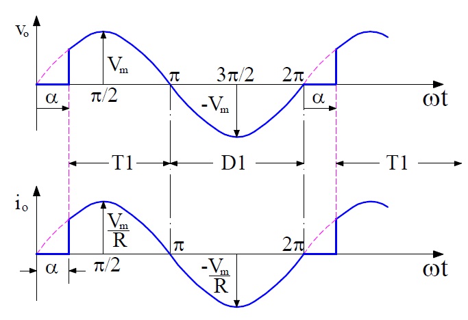
Following points may be noted from the above waveforms:
- By having a control on the firing angle α, the load voltage may be controlled. It may be seen from the output waveform that, there is no control on the negative half cycle of the input voltage. This is the reason, a single phase half wave AC voltage controller is also known as single phase unidirectional voltage controller.
- The positive and negative half cycle of the load voltage & current are not identical. As a result, DC component is introduced in the supply and load circuit which is undesirable.
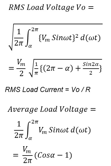
Let us now calculate the rms value of load voltage and current. This will give us an idea of the magnitude of output voltage and current.
Single Phase Full Wave AC Voltage Controller:
A single phase full wave AC voltage controller comprises of two thyristor connected in anti-parallel. The circuit diagram is shown in figure below.

The load is assumed resistive for the sake of simplicity. The input source is VmSinωt.
For the positive half cycle of input source, thyristor T1 is forward biased and hence it is able to conduct provided gate signal is applied. This means that T1 will remain OFF until gate signal is applied. Now suppose, at some angle α (called the firing angle), thyristor T1 is gated. As soon as T1 is fired / gated, it starts conducting and hence, load gets directly connected to the source. This makes load voltage Vo = VmSinα and load current Io = (VmSinα / R) at the instant T1 is fired. From wt = α to π, the load voltage and current follows the input voltage waveform VmSinωt and (VmSinωt / R) respectively.
At wt = π, the load voltage becomes zero and current, also, becomes zero. Since, thyristor T1 is reversed biased after ωt = π and current through it is zero, it gets naturally commutated.
At ωt = (π+α), forward biased thyristor T2 is gated. Hence, it conducts and connected load to the source. The load voltage now follows the negative envelop of the AC input supply and the load current does the same. Thus, the root mean square voltage may be controlled by having a control of firing angle. In this way, voltage control is achieved in AC voltage Controller.
The output waveform for load voltage & current is shown below.

It may be noted from the above waveform that the positive and negative half cycle of the load voltage & current are identical. As a result, DC component is not introduced in the supply and load circuit. This is the main advantage of single phase full wave AC voltage controller.
Single phase full wave AC voltage controller is also know as single phase bidirectional voltage controller. Let us now calculate the rms value of load voltage and current.

Single phase full wave voltage controllers are more suitable to practical circuits. It also overcomes the problem of dc component which is present in supply and load circuit of half wave voltage controller.