Out of all the electrical machines, Induction Motor is the most used machine in industries. More than 90% of motors used in industries are squirrel cage induction motor due to its rugged and maintenance free design. Generally an Induction Motor operates at almost constant speed as the load is varied. But in some industrial applications, speed control of motor is required. This necessitates the requirement of having methods for speed control of induction motor.
Different Methods of Speed Control of Induction Motor
As we know that, rotor of an induction motor rotates at a speed somewhat lower than the synchronous speed. In fact, the rotor speed is governed by the slip. Let us first have a look at the relationship between the rotor speed and slip to arrive at various methods of speed control of induction motor.
If Nr, Ns and s be the rotor speed, synchronous speed and slip respectively, then as per the definition of slip in induction motor,
Nr = Ns(1-s)
But Ns = Synchronous Speed = 120f/P
Nr = (120f/P) (1-s)
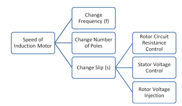
From the above expression of rotor speed, it is clear that speed can be controlled either by changing frequency (f), Number of Poles (P) or the slip (s).
Now, the slip can be changed by the following ways:
- Change Rotor Circuit Resistance
- Vary the Supply Voltage
- Injection voltage of suitable frequency into Rotor Circuit
Thus, speed control of induction motor can be achieved by a total of five different methods:
- VVVF Speed Control
- Pole Changing Method
- Rotor Circuit Resistance Control
- Stator Voltage Control
- Emf Injection in Rotor Circuit
These methods are shown in figure below.
These method of speed control can further be classified on the basis of whether the control is achieved from Stator side or Rotor Side. Following methods lies under Stator side as thses methods are applied on stator winding:
Following methods are employed from rotor circuit side for speed control:
- Cascade Operation of Induction Motor
- emf Injection in Rotor Circuit
- Rotor Circuit Resistance Control Method
It should be noted that, speed control from rotor side is only applicable for Slip Ring Induction Motor.
Speed Control Methods from Rotor Side
Following are the various methods of speed control of induction motor achieved from Rotor side:
Cascade Operation of Induction Motor:
This method is also called the tandem control and obsolete now. In this method, the slip power of induction motor is utilized for speed control. Slip power in induction motor is the power dissipated in the rotor winding as ohmic loss. As we know that, air gap power Pg is sum of mechanical power output and power loss in rotor winding assuming rotor winding to be shorted. Therefore,
Pg = (1-s)Pg + sPg
The first term in the right hand side of above equation is the mechanical power output and second term is called the slip power accounted for losses in rotor winding. This slip power is utilized for speed control in cascade operation of induction motor.
In speed control by cascading of two induction motors, the rotors of the two motors are mechanically coupled. One motor is called Main Motor and the second motor is called auxiliary motor. Main motor stator terminal is connected to the supply main and the slip power of main motor is fed to the stator terminals of auxiliary induction motor through slip ring as shown in figure below.
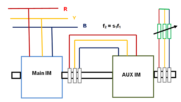
In this way, the slip power of main motor is fed to the auxiliary induction motor at a frequency of f2 = s1f1.
Let us now assume that P1, P2 and s1, s2 be the number of poles and slips respectively. Then for the main motor, synchronous speed is 120f1/P1. Therefore, its speed of rotation will be
Nr1 = (120f1/P1) (1-s1)
Similarly for auxiliary motor, the speed will be
Nr2 = (120f2/P2)(1-s2)
Since main motor and auxiliary induction motor is mechanically coupled, their speed must be equal. This means,
Nr1 = Nr2
(120f1/P1) (1-s1) = (120f2/P2)(1-s2)
Since the slip s2 of auxiliary induction motor is quite small and hence can be ignored as compared to 1. Therefore (1-s2) ≈ 1.
⇒(120f1/P1) (1-s1) = (120f2/P2)
But f2 = s1f1,
⇒(120f1/P1) (1-s1) = (120f1s1/P2)
⇒s1= P2 / (P1 + P2)
Thus the actual speed of main motor is given as
Nr1 = (120f1/P1) (1-s1)
= (120f1/P1) [1- P2 / (P1 + P2)]
= 120f1/(P1 + P2)
From the above expression of speed of main induction motor, we can say that the speed in cascade operation of induction motor is equivalent to the speed of a single motor having (P1 + P2) poles. Since in this scheme, the torque of both main and auxiliary motors are in the same direction, this method is called cumulatively cascaded.
If the phase sequence of the auxiliary motor is changed by interchanging any two leads, it develops torque in a direction opposite to the main induction motor. This scheme is called differentially cascaded operation of induction motor. Under this scheme, the speed of main motor is given as
Nr1 = 120f1/(P1 – P2)
From the above expression, it is obvious that differentially cascaded operation is only possible if main and auxiliary motors have different number of poles i.e. P1 ≠ P2
Speed Control by Injection of EMF in Rotor Circuit:
In this method, the speed of induction motor is controlled by injecting an emf in rotor circuit. The frequency of this injected emf must be at slip frequency at all speeds. This method is applicable only for slip ring induction motor. It must be noted that, when emf is injected in the rotor, the induction motor becomes a doubly excited induction machine. By this method, speed above synchronous speed can be achieved.
To better understand the working principle and effect of injection of emf in rotor circuit, we should consider the phasor diagram of induction motor. Figure below shows the phasor diagram.
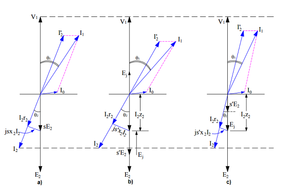
Figure a) represents phasor diagram of induction motor running at slip s and rotor winding short circuited. sE2 is the emf in the rotor winding at any slip s.
As we know that, per phase torque developed by the motor is given as
Te = (E2/ωs)I2cosɵ2
where E2 = EMF generated in rotor winding at standstill condition
ωs = Synchronous speed
Assuming load torque to be constant, then
Te = (E2/ωs)I2cosɵ2 = Constant
Since E2 and ws are constant for a given motor, I2cosɵ2 must remain constant for constant load torque requirement. A constant I2cosɵ2 is shown in above figure a), b) and c) by bottom dotted horizontal line.
In figure b), an emf Ej is injected in phase opposition to the standstill rotor emf E2. Since the speed of motor cannot change suddenly due to inertia, the effect of injection of emf in rotor circuit is to reduce the rotor current from (sE2 / Z2) to [(sE2 – Ej) / Z2] as shown in figure c).
Due to reduction of rotor current, the electromagnetic torque reduces suddenly. As the load torque requirement is constant, a reduction in electromagnetic torque results in reduction of motor speed. Subsequently, the slip increases to a new value (say s’) and hence rotor emf s’E2 increases. Due to this increase in rotor emf, the rotor current again increases till the electromagnetic torque becomes equal to the constant load torque.
Therefore it can be concluded that, injection of emf in phase opposition to E2 results in lower operational speed of induction motor.
If an emf in phase with the standstill rotor emf E2, the rotor current and hence the electrical torque increases. As the load torque is constant, the speed of motor will increase. Thereby the slip will decrease to somewhat lower value (say s’’). Consequently, the rotor emf at slip s’’ will reduce and hence the rotor current will also reduce till the electrical torque balances the load torque.
Therefore it can be concluded that, injection of emf in phase to E2 results in higher operational speed of induction motor.
From the above discussion, it is clear that, it is not the rotor circuit resistance which increases or decreases. Rather it is the rotor circuit current which increase or decreases due to increase or decrease in net rotor circuit emf due to injection of emf in phase or out of phase with standstill rotor emf E2.
Rotor Circuit Resistance Control:
In this method, the resistance of rotor circuit is varied to have speed control. Please read, Rotor Circuit Resistance Control of Induction Motor for detail.
Speed Control Methods from Stator Side
Following are the various methods of speed control of Induction Motor achieved from Stator side:
VVVF Speed Control:
Speed control by changing supply frequency is implemented along with change in supply voltage so as to have a constant flux. This method is therefore called Variable Voltage Variable Frequency (VVVF) method. For detail of this method, please read “VVVF Speed Control of Induction Motor”.
Pole Changing Method:
In this method, the number of poles of induction motor is changed by changing the connection of Stator winding. This method is already discussed in the previous post and you can read here at “Pole Changing Method”.
Stator Voltage Control:
Speed Control of Induction motor is achieved by controlling the stator terminal voltage. This method is useful for loads requiring less starting torque but the torque requirement increases with the load. For detail of this method, please read “Stator Voltage Control of Induction Motor”.