Definition of V-I Characteristics of SCR
A V-I Characteristic of SCR (Silicon Controlled Rectifier) is the voltage current characteristics. The current through the SCR varies as the Anode to Cathode terminal voltage and Gate to Cathode terminal voltage is varied. The graphical representation of current through the SCR and voltage across the anode to cathode terminal is known as V-I Characteristics of SCR.
Circuit Diagram for Obtaining V-I Characteristics of SCR
To obtain V-I characteristics of SCR, its anode and cathode are connected to the source through the load. The Gate and cathode are fed through a separate source which is meant to provide positive gate current from gate to cathode. The elementary circuit diagram for obtaining V-I characteristics of SCR is shown below.
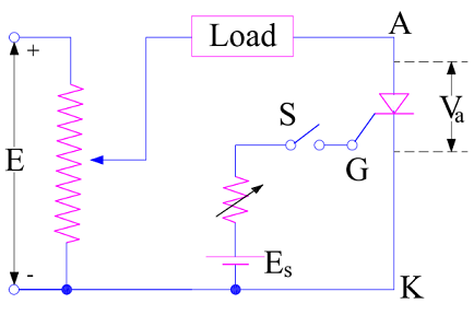
In the above diagram, Anode and Cathode terminals A & K are connected to variable voltage source E through Load and Gate terminal G is connected to the source Es to provide positive gate current through G to K when switch S is closed. Va and Ia represents the voltage across the anode to cathode terminals and current through the SCR. A plot between Va and Ia is drawn by varying the source voltage E and noting the corresponding current through SCR. This plot gives the V-I characteristics of SCR.
Typical V-I Characteristics of SCR
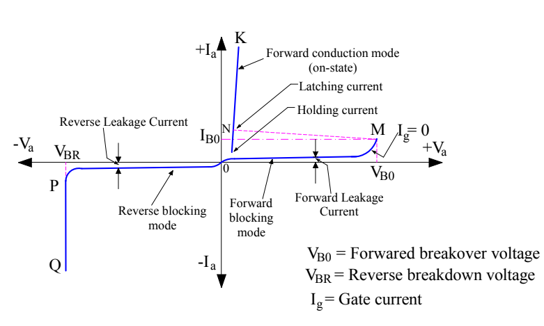
A typical V-I Characteristics of SCR is shown below.
Various Modes in V-I Characteristics of SCR
A careful observation of the V-I characteristics reveal that an SCR has three basic mode of operation: Reverse Blocking Mode, Forward Blocking Mode and Forward Conduction Mode. Let us now discuss each of the three modes one by one.
Reverse Blocking Mode
Reverse Blocking Mode of SCR is that operational mode in which it offers high impedance for current flow and hence do not conduct. An SCR in reverse blocking mode behaves as if an open switch. Hence this mode is also known as OFF state of SCR. It is shown by OP in the V-I characteristics of SCR.
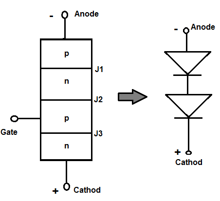
As clear from the V-I curve, the anode to cathode voltage in is negative in this mode. This means that anode terminal is made negative with respect to cathode with switch S open. This leads to reverse biasing of the SCR. Consequently, junction J1 and J3 are reversed biased while the junction J2 is forward biased. The device behaves as if two diodes are connected in series with reverse voltage applies across them.
A small leakage current of the order of mili or micro ampere flows thorough the SCR in this mode. If the reverse voltage is increased, then at some critical voltage an avalanche breakdown takes place at reverse biased junctions J1 and J3 which leads to sudden increase in reverse current. This critical reverse voltage is called Reverse Breakdown Voltage. VBR represents this reverse breakdown voltage in the V-I characteristics. It can be seen that, there is a sharp increase in reverse current at this voltage. This increased reverse current may result in more losses in the SCR which in turn may damage the SCR. Therefore the reverse voltage across the SCR terminals should not exceed reverse breakdown voltage during its operation.
When the reverse voltage is less than VBR, SCR offers high impedance in the reverse direction and hence do not conduct. This is the reason, in reverse blocking mode; an SCR may be treated as an open switch.
Forward Blocking Mode
Forward Blocking Mode is that operational mode of SCR in which it does not conduct even though it is forward biased. The term forward biased SCR implies that its anode terminal is positive with respect to cathode terminal with gate switch S open.
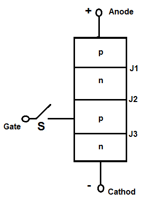
In this mode, the junction J1 and J3 are forward biased but junction J2 is reverse biased. A small leakage current, called the forward leakage current, flows as shown by OM in the V-I characteristics of SCR in this mode. As the forward leakage current is small, SCR offers high impedance. Therefore an SCR can be treated as an open switch even in forward blocking mode.
Forward Conduction Mode
As we have seen that in Forward Blocking mode, even through the SCR is forward biased, it does not conduct. But the good thing is that, in forward blocking mode, junction J1 and J3 are forward biased and J2 is reversed biased. This means, there are two possibilities for making SCR to conduct in this mode:
- Increase the anode to cathode voltage to such an extent which leads to avalanche breakdown of the reverse biased junction J2.
- Apply positive gate pulse between gate and cathode terminal.
When the forward biasing voltage is increased then at some critical voltage VBO, an avalanche breakdown take place at reverse biased junction J2. This critical voltage is known as Forward Breakover Voltage.
Since junction J1 and J3 are already forward biased, an avalanche breakdown at J2 will result in sudden increase in anode current in forward direction. Hence the point M at V-I characteristics of SCR corresponding to Forward Breakover Voltage VBO will at once shift to point N and then to any point in between N and K. Why in between N and K? Since the anode current in this mode will only be limited by the load, so based on the value of load the anode current will change and may lie at any point in between N and K. Thus NK represents the forward conduction of SCR.
Two transistor modal explain and principal
Nicely explain about SCR characteristics. Well done.
Thank you! Please share.
wonderful Explanation
thank you
masta bhai