SCR Turn on methods are the techniques to bring an SCR in forward conduction mode from forward blocking mode. An SCR in forward conduction mode is characterized by low impedance, low voltage drop across anode & cathode and high anode current. The value of anode current is determined by the load. Thus it allows for the flow of current. Therefore, an SCR in forward conduction mode is called its ON state and may be treated as a close switch. SCR is a popular member of thyristor family. It is so popular that the word thyristor and SCR are used as synonymous. Therefore the turn on methods described in this article is applicable for SCR as well as Thyristor.
There is mainly five different methods turn on methods of SCR:
- Forward Voltage Triggering
- Gate Triggering
- dv/dt Triggering
- Temperature or Thermal Triggering
- Light Triggering
You may notice the word triggering in the name of SCR turn methods. In fact, triggering itself means to bring the SCR or thyristor to ON state from its OFF state. Now we will discuss each of the SCR turn methods one by one.
Forward Voltage Triggering
Carefully read the name of this method. It says “forward voltage triggering”. This means we will make SCR ON by applying forward voltage across its terminals. What does this mean? This simply means that we will make it forward biased and will increase this bias voltage till SCR gets ON. Lets us now see how increasing forward bias voltage make SCR ON.
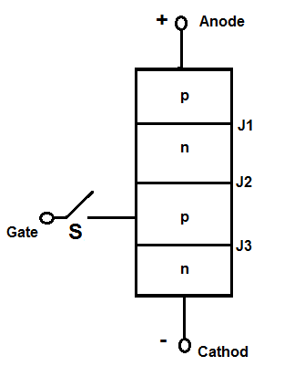
In a forward biased SCR or Thyristor, junction J1 and J3 are forward biased whereas junction J2 is reversed bias. Therefore, increasing this bias voltage will narrow down the width of the depletion region of junction J2 and at a particular voltage, this depletion region will vanish. At this stage, reversed biased junction J2 is said to have avalanche breakdown and this voltage is called the forward breakover voltage. The name forward breakover voltage is given as at this voltage the V-I characteristics of SCR breaks and shifts to its ON position. Refer the V-I characteristics of SCR shown below.
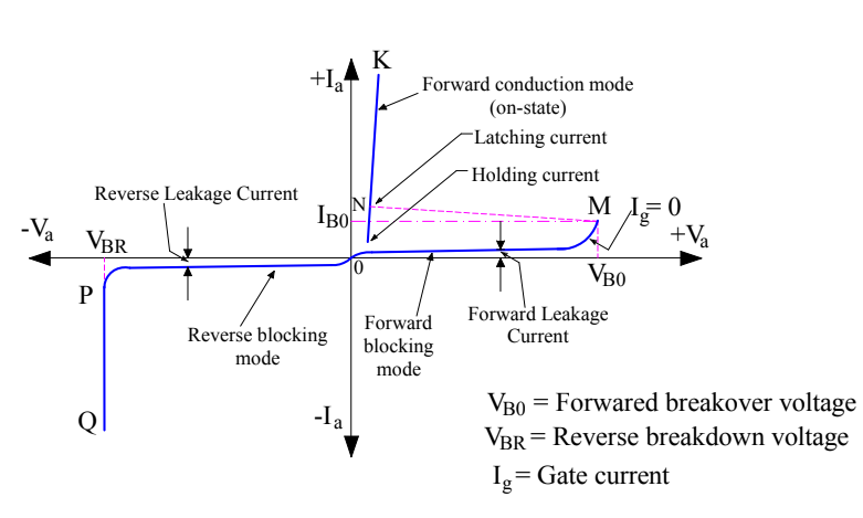
You may notice that at forward breakover voltage VBO, the V-I curve breaks at point M and shift to its On position N with forward breakover current IBO. This is the reason; this critical voltage is called forward breakover voltage.
As soon as avalanche breakdown at junction J2 occurs, current starts flowing from anode to cathode of SCR. The value of this anode current is only limited by the load. Thus SCR is now in its conduction mode in forward direction i.e. from anode to cathode. This is forward triggering method of turning SCR ON.
Normally this method is not used to turn on SCR as it may damage it. Generally the forward breakover voltage is less than reverse breakdown voltage and hence reverse breadwon voltage is considered as final voltage rating while designing SCR. It must also be noted and bear in mind that, once avalanche breakdown take place at junction J2, the blocking capability of J2 is lost. Therefore if anode voltage is reduced below forward breakover voltage, the SCR will continue to conduct. The SCR can now be turned off by bringing its anode current below a certain value called the holding current.
Gate Triggering
Gate triggering is the method in which positive gate current is flown in forward biased SCR to make it ON. Gate triggering is in fact the most reliable, simple and efficient way to turn on SCR. In this method, positive gate voltage between gate and cathode terminals are applied in forward biased SCR which establishes gate current from gate terminal to cathode.
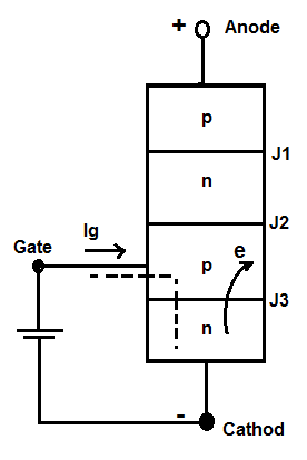
When positive gate current is applied, gate p layer is flooded with electrons from the cathode (n side). This is because the cathode n layer is heavily doped as compared to gate p layer. Since junction J1 and J3 are already forward biased, the injected electrons in gate p layer may reach junction J2 and hence reduces the width of depletion region. This result is reduction of forward breakover voltage. In fact, the more the injected electrons in gate p layer, the more will be chance of electrons reaching J2. This means the more the value of gate current, the more will be reduction in forward breakover voltage. Thus gate current and forward breakover voltage are inversely proportional.
Please refer the figure below. This is the V-I characteristics of DSCR for different values of gate current Ig.
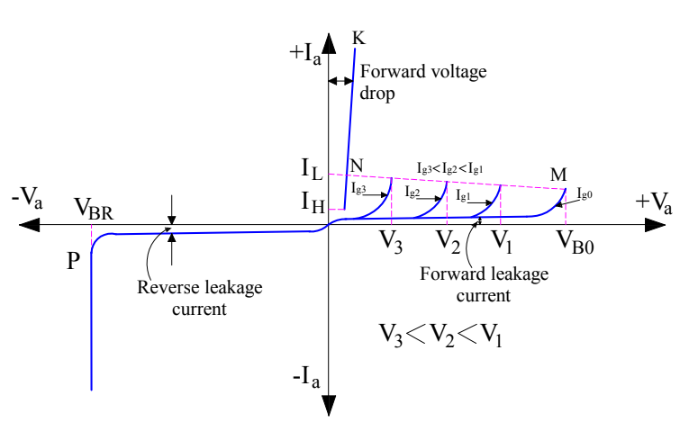
Following points can be observed and noted from the above curve:
- When the gate current Ig is zero, the forward breakover voltage is VBO.
- As gate current increases from zero to Ig1, the forward breakover voltage reduces from VBO to V1. Similarly, its value reduces from V1 to V3 as the gate current increases from Ig1 to Ig3.
Thus the SCR may be turned on by applying gate current. It should be noted that SCR is turning on due to forward breakover voltage though this voltage is reduced considerably due to positive gate current.
Once SCR starts conducting in forward direction, reversed bias junction J2 no longer exists. Therefore, no gate current is required for SCR or thyristor to remain in ON state. Therefore if gate current is removed, the conduction of current from anode to cathode is not affected. However, if gate current is reduced to zero before the rising of anode current to a specific value called the latching current, the SCR or thyristor will turn off again. This means we should not make gate current off until anode current has crossed latching current.
|
Latching current is defined as the minimum value of anode current which must be attained during turn on process of SCR to main the conduction even when gate current is removed. |
Once SCR or thyristor starts conductiong, gate losses its control. The SCR or thyristor can now be turned OFF only if the anode current reaches below a specified value of anode current. This value of anode current below which SCR gets turned OFF is called Holding Current. As can be seen from the V-I characteristics of SCR, the value of latching current is more than the Holding Current.
|
Holding Current is defined as the minimum value of anode current below which it must fall for turning OFF the SCR or Thyristor. |
dv/dt Triggering
dv/dt Triggering is the technique in which SCR is turned ON by changing the forward bias voltage with respect to time. dv/dt itself means rate of change of voltage w.r.t time.
As we have discussed earlier in this post, junction J2 is reversed biased in a forward blocking mode of SCR. A reversed biased junction may be treated as a capacitor due to presence of space charges in the vicinity of reversed biased junction. Let us assume its capacitance to be ‘C’ farad. The charge on capacitor, voltage across the capacitor and capacitance are related as below:
Q = CV
Differentiating both sides w.r.t time, we get
dQ/dt = C(dV/dt)
But current I = dQ/dt
⇒ I = C(dV/dt)
Thus the current through the reversed biased junction J2 is directly proportional to (dv/dt). Therefore if the rate of rise of forward voltage i.e. (dv/dt) is high, the charging current I will also be high. This charging current acts like gate current and turns ON the SCR or thyristor even though the gate current is zero. If should be noted that, it is rate of rise of voltage which is responsible for turning the SCR ON. It is independent of magnitude of voltage. The voltage may be low, but the rate of its rise should be high enough to turn SCR ON.
Temperature Triggering
Temperature triggering is also called thermal triggering. As we know that in reversed biased junction a reverse saturation current flows whose value depends on the temperature of the junction. This means, in forward blocking mode of SCR or thyristor, there will be a flow of reverse saturation current across the junction J2. This current will increase the temperature of the junction which in turn will result in further increase in reverse leakage current. This increased leakage current will again increase the junction temperature and hence will further increase the reverse leakage current. Thus, this process is cumulative and will eventually lead to vanishing of depletion region of reversed biased junction J2 at some temperature. At this temperature, the SCR will get turn ON.
Light Triggering
In light triggering, a pulse of light of suitable wavelength guided by optical fibers is irradiated to turn SCR ON. A recess or niche is made in the inner p layer for light triggered SCR as shown in figure below.
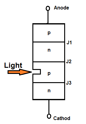 When this niche is irradiated, free charge carriers i.e. electron and hole pairs are generated. If the intensity of irradiated light is exceeds a certain value, forward biased SCR is turned ON. Note there that, irradiated light produces free charge carries which is just like in case of gate current. There charge carries move near the reversed biased junction J2 and reduces the forward breakover voltage. This is the reason, the SCR gets turned ON. The SCR which is turned ON by using light is called Light Activated SCR or LASCR.
Explain turn on methods of scr
The article already discusses Turn ON Methods of SCR.