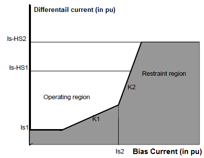
If you ever have seen the setting of Differential Protection of Transformer, you might have noticed two settings shown as Is-HS1 (called High Set 1) and Is-HS2 (called High Set 2). In this post I will be discussing about the significance of these two parameters and its calculation for transformer differential relays.
High Set 1(Is-HS1) is the minimum value of current for which the differential relay will operates without considering 2nd and 5th harmonic blocking. But differential and bias current is taken care. The relay will only issue trip command if the value of differential and bias current is inside the operating region in its slope characteristics. This means, high set 1 is applicable during charging and overflux condition of transformer. During charging, transformer draws a heavy inrush current which mainly comprises of 2nd harmonic current. This charging current may cause the value of differential current to exceed the low set value ad hence may operate it. To avoid this, 2nd harmonic blocking is provided. To read the detail of harmonic blocking, you are requested to refer Harmonic Restraining in Differential Protection.
Calculation of Is-HS1:
To set the value of Is-HS1, care must be taken that differential element is not actuated during charging of transformer. Therefore knowledge of value of transformer inrush current is must. Since the value of inrush current depends on various factors viz. remanance flux present in transformer, point on wave switching (point on voltage wave where the transformer is switched on), number of transformer connected in parallel etc., therefore a worst case is assumed to calculate the setting value of high set 1 i.e. Is-HS1.
As a worst case, maximum fault current is assumed. Let us take an example for better understanding. Let Is-HS1 setting of a 70 MVA, 220 kV / 6.9 kV transformer is to be calculated. Let the per unit impedance of this transformer is 12%.
= Base MVA / Percentage Impedance
= 70 / 0.12
= 583.33 MVA
Maximum per phase Fault Current in HV side
= 583.33 MVA / (1.732×220)
= 1531 A
Let the 400/1 CT is used in HV side for differential protection of transformer. Therefore, the CT secondary current corresponding to the fault current
= 1531 / 400 A
= 3.82 A
The above CT secondary current should be multiplied by the CT matching factor to get the per unit setting value of Is-HS1. So we should now calculate the CT Matching Factor. Please read “CT Matching Factor in Differential Protection” to get this value. I am directly using its value here.
CT matching factor = 2.17
Setting value of Is-HS1
= 3.82×2.17
= 8.3 pu
Thus the setting of Is-HS1 should be 8.3 pu.
Calculation of Is-HS2:
High Set2 or Is-HS2 is basically the upper value of differential current in relay slope characteristics. This means relay will check if the fault is lying under its operating region or not for its actuation if the fault current is less than Is-HS2. If the value of fault current is more than or equal to Is-HS2, the relay will instantaneously actuate even if 2nd and 5th harmonic blocking are existing. You may think that this is similar to Is-HS1 so why do we need Is-HS2? Actually Is-HS1 will actuate the differential element if the fault point is within the operating region of relay slope characteristics whereas Is-HS2 will actuate the differential element even if the fault point is not in the operating region. To be straight forward, relay slope characteristics is only defined up to Is-HS2. Beyond this, relay slope characteristics is not defined.
Now you might think why do we need to incorporate Is-HS2 or what is its significance? This really a good thing which must be clearly understood. Let us assume an example. Figure below shows a case where two CTs 1 &2 are wired to differential protection of 70 MVA Transformer. As we know that this protection is meant to protect transformer from internal fault. So if there is any fault in the transformer, the protection will operate to isolate the transformer.
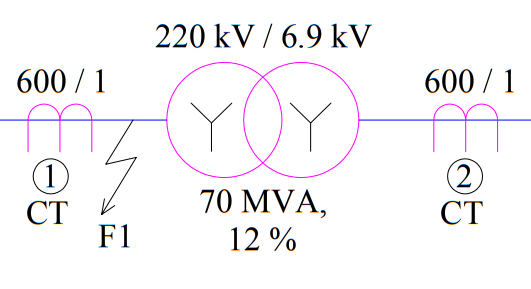
Now consider a fault at point F1. Notice that this fault is not internal to the transformer but it is within the protection zone of differential. Further, in this case the fault current is not limited by the transformer impedance; rather it is limited by system to source impedance. This fault will result in very high value of fault current much more than 1531 A calculated above. To actuate differential relay in such cases for which slope characteristics is not defined, setting of Is-HS2 is required. Generally the value of Is-HS2 is chosen around 1.3 to 1.4 times of Is-HS1. But care must always be taken while calculating the setting value of Is-HS2 that it should not operate the differential element for through fault condition. As you can see here in our example that we have chosen the value of Is-HS1 on the basis of maximum fault current, therefore setting of Is-HS2 as 1.3 times of Is-HS1 will never operate in case of through fault.
There is one more point which should be understood here. Suppose instead of two different CTs 1 & 2, two Bushing CTs are used for differential protection. If Bushing Current Transformer is used, there obviously there will not be any external fault which will lie within the differential zone. Hence no case will exist similar to one shown in above figure. This means setting of Is-HS2 is not required.
Hope you understand whatever I wanted to share. Since the topic is vast, you feedback and suggestion is welcome for improvement. Thank you!
excellent and rather easy explanation. keep up the good work.
Thank you very much! Please share if you really like it.
REALLY NICE EXPLANATION. I LIKED IT..
Thanks very much
Kindly share. It will help us.
Let the 600/1 CT is used in HV side for differential protection of transformer. Therefore, the CT secondary current corresponding to the fault current
= 1531 / 400 A => this to b e 1531 / 600 A
Thank you for pointing the typo. Same corrected.
Hi, your explanation is really helpful. I just have a theoretical question. The part where you derive max MVA (583.33MVA) & max fault current(1531A)from %Z. Is it a fact that power transformer can really produce this max MVA under rated voltage short circuit condition? Or is this a theoretical maximum possible value?
Thank you for imparting clarity in easy to understand words.
Kindly share if you like it.