Equation of power flow through an inductive load provides the relationship between the sending end voltage, receiving end voltage, line parameters viz. inductance and resistance of line and the impedance angle. The equation is general and can be well applied for Synchronous generator,Synchronous Motor and Transmission Line with slight but appropriate changes. In this post we will be deriving the equation for power flow through an inductive load which is applicable and can be used for synchronous generator as well as transmission line.
Let us assume a transmission line. Let the sending and receiving end voltages are E1 and E2 respectively. The line impedance is assumed to be Z. The equivalent circuit of this transmission line (neglecting the shunt capacitance) is shown below.

In the above figure, Source and Load is written instead of sending and receiving end. This is done to illustrate that the figure is applicable for transmission line and synchronous generator. For synchronous generator, sending end will be the source while the receiving end will be the Load. Line impedance will be replaced by synchronous impedance. In this post,bold signs mean their phasor form.
For the flow of current from E1 to E2,
E1 = E2 + IZ
I = (E1 – E2) / Z
= E1/Z – E2/Z ……….(1)
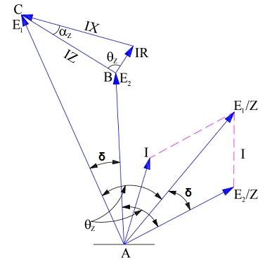
The phasor diagram of the above equivalent circuit will be as shown below.
Let us now calculate the active power P1 at the source (sending end) end E1 of the impedance. Since active power is equal to multiplication of voltage and component of current in phase with voltage, therefore
Active Power, P1 at source end
= E1 (Component of I in phase with E1) ……..(2)
So we need to find the value of current component in phase with source voltage E1. From (1), it is clear that the line current or armature current (for generator) is difference of two values (E1/Z) and (E2/Z). This means, we individually have to find their values and get them subtracted to get the actual value of current I flowing from E1 to E2. For this, refer the phasor diagram.
Component of (E1/Z) along the E1
= (E1/Z)CosƟz
Component of (E2/Z) along the E1
= (E2/Z)Cos(δ+Ɵz)
From equation (1),
I = [(E1/Z)CosƟz – (E2/Z)Cos(δ+Ɵz)]
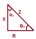
But CosƟz = (R/Z) and Ɵz = (90 – αz)
Therefore, current I
= [(E1/Z)CosƟz – (E2/Z)Cos(δ+Ɵz)]
= [(E1R/Z2) – (E2/Z)Cos{δ+(90 – αz)}]
= (E1R/Z2) + (E2/Z)Sin(δ – αz)
Now, Active Power P1 at source end from (2)
= (E12R/Z2) + (E1E2/Z)Sin(δ – αz) ……(3)
The above expression gives the equation of power flowing from the source or sending end.
The equation for power flowing to the receiving or load end can be derived in the similar fashion. Let us find.
The power P2 flowing at the load end E2 through impedance E2,
P2 = E2 (Component of I in phase with E2)
Component of current I in phase with E2
= [(E1/Z)Cos(Ɵz – δ) – (E2/Z)CosƟz]
But,
P2 = E2 (Component of I in phase with E2)
= (E2E1/Z)Cos(Ɵz – δ) – (E22/Z)CosƟz
= (E2E1/Z)Cos{90 – (δ+ αz)} – (E22/Z)CosƟz
= (E2E1/Z)Sin (δ+ αz) – (E22R/Z2) ……..(4)
The above expression gives the equation for power flow at the load end or receiving end. For power flow through a cylindrical rotor synchronous generator or alternator, E1 should be replaced by Ef, E2 by Vt and Z by Zs. Here, Ef, Vt and Zs are Excitation Voltage, Armature Terminal Voltage and Synchronous Impedance respectively.
Power input to the Generator will be the power at the source i.e. P1. Therefore,
Power Input of Generator Pig from (3),
= (Ef2R/Z2) + (EfVt/Z)Sin(δ – αz)
Since synchronous impedance,
Zs = ra + jXs
So, Power Input of Generator Pig
= (Ef2ra/Zs2) + (EfVt/Zs)Sin(δ – αz)
Power Output of Generator Pog from (4),
= (EfVt/Zs)Sin(δ+ αz) – (Vt2ra/Zs)
Since the resistance of armature winding is quite low as compared to its inductance, therefore for simplicity this armature resistance ra may be ignored. Hence Zs = jXs and ra = 0.
Power Output of Generator Pog
= (EfVt/Xs)Sin(δ+ αz)
Since ra = 0, therefore αz = 0 as can be seen from impedance triangle.
Power Output of Generator Pog
= (EfVt/Xs)Sinδ
You must be very much familiar with the above power equation of the generator. This is very useful equation and we draw power angle curve of generator using the above equation. Note that angle δ is the angle between excitation emf Ef and terminal voltage Vt, hence it is load angle for generator.