Rotating magnetic field is magnetic field which rotates in space about some point or axis. The North and South poles continuously rotates with a specific speed, called synchronous speed. All poly phase electrical machines are associated with rotating magnetic field in the air gap. Therefore, an understanding of rotating magnetic field produced by poly phase winding is very important to analyze and understand the principle and operation of electrical machine viz. Synchronous Machine and Induction Machine.
Condition for Generation of Rotating Magnetic Field
When a balanced poly phase current flows in the balanced poly phase winding, a rotating magnetic field is produced. The necessary condition for generation of rotating magnetic field is that “the time angle displacement between the currents and space angle displacement between the winding axes must be equal.”
Let us consider an example for better understanding of the above mentioned condition. In the figure below, three coils a, b and c with their magnetic axis coincident are excited by three phase balanced current Imsinωt, Imsin(ωt-120°) and Imsin(ωt+120°).
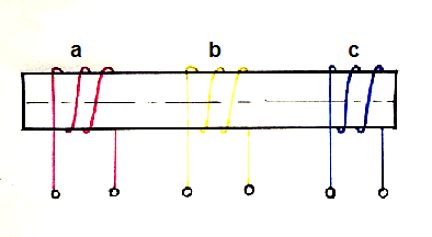
In this case, the time angle displacement between the currents is 120 degree but the space angle displacement between the winding axes zero. Therefore, rotating magnetic field will not be produced.
How Rotating Magnetic Field is Produced?
In a three phase machine, the three windings are displaced from each other by 120 degree along the air gap periphery. A typical three phase, 2 pole machine with three windings a, b and c is shown below.
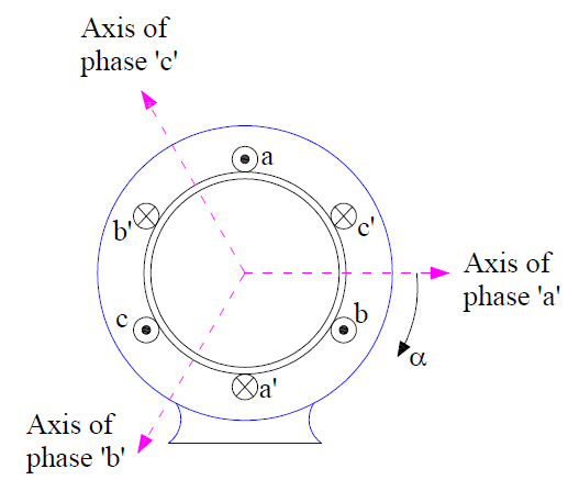
The three phase windings a, b and c is represented by three full pitched coils aa’,bb’ and cc’ in the above figure. The concentrated full pitched coil aa’, bb’ and cc’ represents R, Y and B phase respectively. A current in phase ‘a’ winding produces magnetic field directed along the magnetic axis of coil aa’. Similarly, current in phase ‘b’ and ‘c’ windings produces magnetic flied directed along the magnetic axis of coil bb’ and cc’ respectively.
Let us assume that a three phase sinusoidal current flows in the three windings ‘a’, ‘b’ and ‘c’ as shown in figure below.
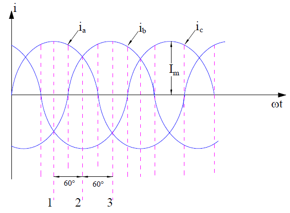
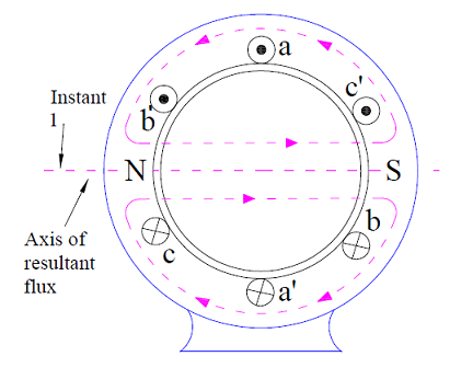
At instant 1, the current in the phase ‘a’ is positive whereas negative in phase ‘b’ and ‘c’. The value of current in phase ‘a’ is Im whereas those in other two phases are –Im/2. Under this condition, the resultant magnetic field will be directed along the magnetic axis of coil aa’ as the current in phase ‘a’ is maximum. This magnetic field creates two poles on the stator of the machine. This is shown in figure below.
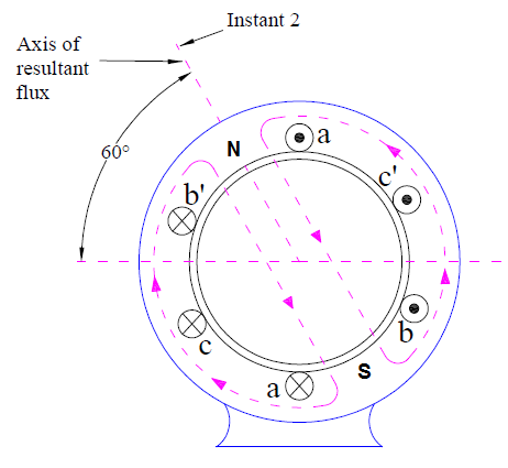
At instant 2, the currents in the three phases are Im/2, Im/2 and –Im. Thus the maximum current is flowing in phase ‘c’ and is negative. Therefore the resultant magnetic field at this instant of time will be directed along the negative of the magnetic axis of coil cc’. This is shown in figure below.
At instant 3, the currents in the three phases ‘a’, ‘b’ and ‘c’ are –Im/2, Im and –Im/2 respectively. Therefore the maximum current is flowing in phase ‘b’ and hence the resultant magnetic flied will be directed along the magnetic axis of coil bb’. This is shown in figure below.
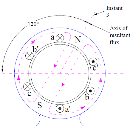
From the above three cases, it can easily be seen that the magnetic poles created is rotating in space with change in phase current. The direction of rotation of rotating magnetic field is determined by the phase sequence of three phase current. In our example, three phase sequence is abc and hence the magnetic field is rotating in clockwise direction. If the phase sequence is changed to acb, the magnetic field will rotate in counter clockwise direction.
It is also clear from the above discussion that the distance traveled by rotating magnetic field is equal to two pole pitch or 4π radian in space in one cycle of current. This is because the generated poles align themselves at the initial position after one time period of phase current.
Thus, for a P pole machine, the distance travelled by the filed in one time period T of current will be equal to one pole pitch = (4π / P) radian. Therefore, the speed Ns of rotating magnetic field is given as
Ns = (4π / PT) radian/sec.
But T = 1/f, where f is frequency of phase current or supply
Ns = (4πf / P) radian/sec.
We know that 1 revolution = 2π radian,
Therefore speed of rotating magnetic field Ns = 2f/P revolution/sec.
= (120f/P) r.p.m
Thus, the rotating magnetic field revolves with a speed of (120f/P) r.p.m for a P pole machine. This speed is called Synchronous Speed.
Hope the concept of rotating magnetic field and its production in three phase electrical machine like Induction Motor is clear. If you have any doubt, please write in comment box.
Magnitude of Rotating Magnetic Field
The magnitude of rotating magnetic field is given in terms of maximum mmf of any one phase when current in that phase is maximum. Let the this maximum mmf is Fm. In general, m-phase currents flowing in the m-phase winding results in a rotating mmf wave of constant amplitude equal to (m/2)Fm.
Thus, for a three phase machine, the magnitude of rotating mmf wave FR is given as
FR = (3/2)Fm
But Fm = (4√2/π)(kwNphI)/P ATs/pole, where kw is winding factor, Nph is number of series turns per phase and I is the current.
Thus, FR = (2.7kwNphI) / P ATs/pole
Important Points to Remember
The resultant mmf produced by a three phase currents flowing in three phase windings, consists of following components:
- Constant amplitude fundamental mmf wave rotating in the air gap with synchronous speed.
- Triplen harmonics viz. 3, 9, 15 etc. are absent in the resultant rotating mmf wave in the air gap.
- Fifth harmonic mmf wave is sinusoidally distributed in the space with constant amplitude of one fifth of that of fundamental component i.e. (FR/5). This component rotates in a direction opposite to that of fundamental component at a speed of one-fifth of the fundamental synchronous speed.
- Seventh harmonic mmf wave is sinusoidally distributed in the space with constant amplitude of one-seventh of that of fundamental component i.e. (FR/7). This component rotates in the direction of fundamental component at a speed of one-seventh of the fundamental synchronous speed.
Hello,
I am designing the physical layout of a Faraday homopolar motor in an orientation such that the rotating permeant magnet of the generator doesn’t interfere which the stationary magnetic field of the homopolar motor or visa versa.
any temporal or spacial ideas?
Very important to me. Thanks.
Thank you!