The resonant frequency formula for series and parallel resonance circuit comprising of Resistor, Inductor and capacitor are different. In this article, we will go through the resonant frequency formula for series as well as parallel resonance circuit and their derivation. We will also discuss the method to find the resonant frequency for any given circuit with the help of some examples.
Resonant Frequency Formula – Series Resonance Circuit
The formula for resonant frequency for a series resonance circuit is given as
f = 1/2π√(LC)
Derivation:
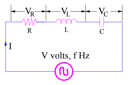
Let us consider a series connection of R, L and C. This series connection is excited by an AC source.

Let us first calculate the impedance Z of the circuit.
Z = R + jωL – j/ωC
= R + j(ωL – 1/ ωC)
Under the condition of resonance, the circuit is purely resistive. This means, the imaginary part of the impedance Z will be zero during resonance condition or at resonant frequency. You should always keep this in your mind while calculating resonant frequency for a given circuit.
This means,
(ωL – 1/ ωC) = 0
ωL = 1/ωC
ω2 = 1/(LC)
ω = 1/(LC)
As, we know that
ω = 1/2πf
Therefore, f = 1/2πω
Resonant Frequency (f0) for Series Resonance Circuit,

Notice that, there is no need to draw phasor diagram. You only need to find the impedance and make imaginary part of impedance zero to find the resonant frequency of given circuit. We will apply the same technique for parallel resonance circuit too.
Resonant Frequency Formula – Parallel Resonance Circuit
The formula for resonant frequency for a parallel resonance circuit is given as,

Derivation:
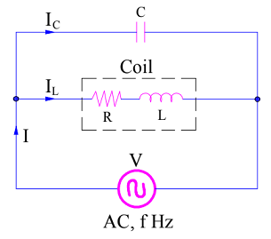
Let us consider a parallel resonance circuit as shown below. Our target is to find the resonant frequency formula for this circuit.


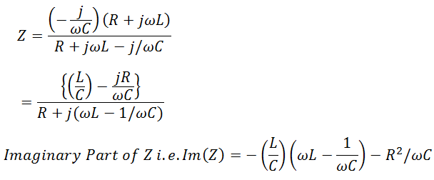
Again, first of all, we will find the impedance Z of the circuit.


Equating Imaginary Part to zero, we get
⇒ -(ωL2)/C + L/(ωC2) – R2/(ωC) = 0
⇒ -ω2L2C + L – R2C = 0
⇒ ω2L2C = L – R2C
⇒ ω2 = 1/(LC) – R2/L2
Since, ω = 1/2πf
Resonance frequency f0


So, how simple is to find the value of resonance frequency? Isn’t it? Let’s solve some example to have better understanding.
Example:
Find the resonant frequency for the circuit shown in figure below.


The values RL, L, R and C are 1 Ohm, 1 Henry, 0.5 Farad and 1 Ohm respectively.
Solution:
As discussed, first of all, we will find the impedance and then we will equate the imaginary part of Z to zero to get the value of resonant frequency. But, let’s be a bit cleaver. As the circuit is parallel connection of elements, it is better to find Admittance Y instead of impedance for the sake of ease in calculation.
Y = 1/R + jωC + 1/(RL+jωL)
= 1/R + jωC + (RL – jωL)/( RL2+ω2L2)
Imaginary Part of Y
= ωC – ωL/( RL2+ω2L2)
To get resonant frequency, make imaginary part of admittance zero.
ωC – ωL/( RL2+ω2L2) = 0
(RL2+ω2L2) = L/C
ω2 = (1/LC) – (RL2 / L2)
Now, put the value of C, L and RL
ω2 = 1
ω = 1 rad/sec. (Ans.)
If I am correct the freq for an LC circuit will be slightly different than freq of an LCR circuit if the L and C parts are the same value ? This is significant when setting a power matching circuit for example in feeding a radio aerial system which needs the current correcting using conjugate methods in the matching network. Sadly everybody including the manufacturers still call this an ATU when it is in reality an AMU Aerial (Antenna) Matching Unit. This confuses everybody. The current in the reactive part is watt-less current and the current in the radiation resistance is radiating and therefore real power. The real current comes from its holding from the L&C storage of the resonant system part ! They are 90 degrees apart !
good, it’s helpful for me 😊
good explanation, it is help full for me.😊👍