Series connection of SCR is required where we want to meet the increased voltage requirement by using various SCRs. Let us make it easier to understand. Suppose the SCR available with us is having a voltage rating of 600 V but the voltage rating required for our application is 2400 V. In this case, if four or SCRs are connected in series then this voltage requirement can be met.
The way of connection is similar as we do in series connection of battery. This means in series connection, cathode of one SCR is connected to anode of other SCR and so on.
Series Connection of SCR:
For series connection of SCR, the requirement is that all the SCRs should have identical V-I characteristics. This is required to get uniform voltage distribution across the individual SCR units in the string. You might think what is string? String is nothing but the series connected SCRs. It is same like we talk of string of insulators. But when we talk of string, there is an associated terminology called string efficiency. In series connection of SCR, effort is made to achieve higher string efficiency. The more the string efficiency, the more will be voltage equalization across the individual SCR units in the string. Ideally the value of string efficiency is 1. But practically we cannot ever achieve this value of unity. The reason for this is described below.
- Difference in V-I or static characteristics of SCR
- Difference in Dynamic Characteristics of SCR
Difference in V-I or static characteristics of SCR:
Two SCRs having the same name plate rating and make cannot have the same V-I characteristics. The V-I characteristics of two identical SCRs is shown below.
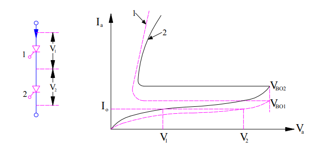
It can be seen from the above figure that for the same value of forward leakage current I0, the forward blocking voltage of SCR1 is more whereas it is less for SCR2. This means, voltage across SCR1 will be more than that across SCR2 in a string. Hence the voltage which the string can block will be (V1+V2). However, as per the name plate rating this forward blocking voltage of string should be 2V1 as the SCRs are identical having the same forward blocking voltage. Therefore string efficiency of SCR will become
String Efficiency
= (V1+V2) / 2V1
= 0.5[1+ (V2/V1)]
This shows that even though the SCRs have the identical rating, voltage shared by each unit in the string is not same. Hence the string efficiency is less than unity.
Thus the main reason for non-uniform voltage distribution across each SCR unit in a string is difference in their V-I characteristics.
Now the question arises, is there no way to equalize the voltage distribution? The answer is “Yes, there exist methods to improve the string efficiency of SCR”.
How to equalize voltage distribution across each SCR in series connected string during steady state?
A new word, voltage equalization during steady state. Why new word steady state? This is because, static or V-I characteristics of SCR is the relationship of voltage and current under steady state. Since the unequal voltage distribution is just because of difference in V-I characteristics of SCRs, this means the remedy will be applicable for steady state condition. Let us now move on.
A uniform voltage distribution in steady state is achieved by connecting a suitable resistance in parallel with each of the SCR so that each parallel combination has the same resistance. This obviously will require different value of resistance to be parallel with each SCR which is practically not feasible. But what we can do practically is that we can parallel same value of resistance across each SCR. This resistance connected in shunt with SCR is called static equalizer circuit. This helps in improving the string efficiency under steady state condition. The value of the static equalizing resistance is given as
Where from this value of static equalizing resistance came from? Is it the outcome of a very complicated computation? No friends, it is the outcome of a very simple calculation. So let’s calculate the value of this resistance.
Calculation of Static Equalizing Resistance:
Let us assume that, n SCRs are connected in series. This is shown in figure below.
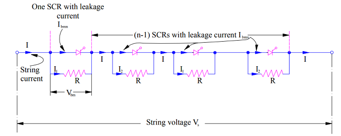
Suppose the SCR1 has the minimum forward leakage current Ibmn and hence maximum forward blocking voltage Vbm and remaining all SCRs have the same forward leakage current Ibmx. Thus the current through resistance R in shunt with SCR1 i.e. I1 will be
I1 = I – Ibmn where I is the string current.
Voltage across SCR1 = I1R
Similarly,
I2 = I – Ibmx
Voltage across (n-1) SCRs = (n-1)I2R
Thus, the string voltage
Vs = I1R+(n-1)I2R …….(1)
We should consider the extreme case from the calculation of resistance R for voltage equalization in string of SCR. In extreme case, the voltage drop across SCR1 will be the maximum forward blocking voltage Vbm. Therefore,
Vbm = I1R
Thus equation (1) becomes,
Vs = Vbm + (n-1)I2R
Let us now put the value of I2 in the above equation,
Vs = Vbm + (n-1) (I – Ibmx)R
= Vbm + (n-1)R [1 – (Ibmx – Ibmn)]
= Vbm + (n-1)I1R – (n-1)R(Ibmx – Ibmn)
Since, Vbm = I1R therefore
Vs = Vbm + (n-1) Vbm – (n-1)R(Ibmx – Ibmn)
= nVbm – (n-1)R(Ibmx – Ibmn)
Thus,
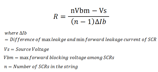
R = [nVbm – Vs] / [(n-1)(Ibmx – Ibmn)]
Match the above expression of static equalizing resistance R with the one stated earlier. Aren’t both same?
Till now we have discussed the unequal voltage distribution due to difference in static or V-I characteristics of SCR in the string and method for improving string efficiency. Now it’s time to discuss the unequal voltage distribution due to difference in Dynamic Switching characteristics of SCR and method to equalize the voltage distribution.
Difference in Dynamic Characteristics of SCR:
I won’t take you a deep drive into the dynamic characteristics of SCR, but you can always read for detail. For the time being, dynamic characteristics refer to turn on and turn off time of the SCR. So if the dynamic characteristics of two SCRs differs, then we will simply understand that their turn on and turn off time are different. Let us investigate the effect of different turn on and turn off time of SCR in a string.
Let us consider two SCRs connected in series. Suppose SCR1 is having less turn on time while the other SCR2 have slightly more turn on time. Suppose both the SCRs are sharing equal forward voltage i.e. (Vs/2) where Vs is the string voltage.
As soon as both SCRs are gated, SCR1 will turn on earlier and hence the voltage drop across its terminals will drop whereas the voltage across SCR2 will become Vs. SCR2 will turn on after some time. Till the time SCR2 is turned off, there is an unequal voltage sharing.
Similarly, during turning off there will be an unequal voltage distribution across each SCR in the string.
How to equalize voltage distribution across each SCR in series connected string during transient or switching state?
To understand the method for voltage equalization across each SCR in a series connected string during turn on and turn off time, first we should investigate the reason for unequal voltage sharing among SCRs.
The factor which is responsible for unequal voltage sharing is capacitance of reverse biased junction during turn on and turn off process. This capacitance of reversed biased junction is called self capacitance of thyristor or SCR. Since the self capacitance of different SCR differs, hence voltage sharing also differs. Thus our target should be to match the capacitance for all SCR units in string anyhow.
We can connect a fixed value of capacitance across each SCR so that the combined value of capacitance of parallel connection is same for all SCR units. Therefore, the voltage sharing will be equalized among all the SCR.
When SCR is in forward blocking mode, this shunt capacitor gets charged up to supply voltage and as soon as the SCR starts conduction, this charged capacitor discharges. The value of this discharge current may be very high. Therefore, to limit the discharge current, a limiting resistance Rc is also connected in series with the shunt capacitor. Combination of Rc and Capacitor C is called dynamic equalizing circuit.
But as expected, the limiting resistor should come in picture when SCR is in forward conduction mode. To implement this, a diode is connected in parallel with the limiting resistor Rc as shown in figure.
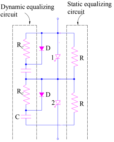
When SCR is under forward blocking mode, the diode is forward biased. Hence the resistor Rc is bypassed. But as soon as SCR starts conducting, the diode get reversed biased due to capacitor voltage. This forces capacitor discharge current to flow through resistor Rc. Thus this circuit protects SCR from dv/dt as well as di/dt.
Thank you friends! If you like the post, please share it.
Excellent sir ,it is very useful website..
In detail..
Thank you Sajjan! Please share if you like it.
What is the equation of dynamic equalizing circuit?
Thanxx sir👌👌👌👍🇮🇳🕶🕶🕶🕶