Armature winding in an electrical machine is the winding which carries the load current. Under no-load condition, the armature current is zero. But as the machine is loaded, load current flows through the armature winding and creates magnetic flux. The effect of armature winding mmf or flux on the main working flux created by field poles is called the armature reaction. This article outlines the armature reaction in synchronous machine or alternator.
To better understand the armature reaction in synchronous machine, it is essential to first understand the internal happening. For this purpose the alternator operation is considered under different operating power factor and loads as follows:
- No-load Operation
- Unity power factor (pf) load
- Zero power factor lagging load
- Zero power factor leading load
- Lagging power factor load
Let us now investigate the effect of armature reaction for the above mentioned cases one by one.
No-load Operation:
As mentioned earlier, the current through the armature winding of alternator is zero for no-load operation; therefore there will not be any armature reaction. When the field winding is excited by a DC source and the alternator / generator is brought up to synchronous speed by adjusting the speed of prime-mover, no load voltage or excitation voltage is generated across the alternator armature terminals. The value of no-load or excitation armature terminal voltage is given as
Ef = √2πfNphKwØf
Where Ef, Nph, Kw and Øf are excitation voltage, number of series turns per phase, winding factor and filed flux respectively.
This generated excitation voltage across the armature terminal lags behind the field flux Øf by 90 degree. In general, the emf generated by the filed flux always lags behind the field flux by 90 degree in any machine.
Unity Power Factor Load:
In order to understand the effect of armature mmf on the field mmf wave, let us consider a two pole cylindrical rotor alternator as shown in figure below.
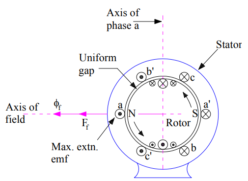
In the above figure, concentrated full pitched coils aa’,bb’ and cc’ on stator represents the three phase winding a, b & c. The filed winding on rotor is fed by DC source for setting up working or main filed mmf. Field current indicated by cross and dot in the field winding on rotor, creates field mmf Ff and field flux Øf which are sinusoidally distributed along the air-gap periphery. This filed flux creates North (N) and South (S) pole on the rotor.
As we know that emf induced in a coil is maximum when its coil sides are lying under maximum flux position. In view of this, maximum emf will be generated in coil aa’ as its coil sides a and a’ are lying under peak flux density. This generated emf is shown by dot and cross at a & a’ respectively assuming anti-clockwise rotation of rotor. Since coil sides b’ and c’ are also under the influence of N pole, emf induced in these coil are represented by a dot. However their magnitude will be less than the maximum value. This emf generated by Øf alone is called the excitation voltage.
Now, when this alternator is connected to a balanced 3 phase load, a balanced three phase current starts flowing in the three phases of alternator. As the load is of unity power factor, this means that excitation voltage Ef and armature current Ia will be in phase. This can also be interpreted in another way like excitation voltage and armature current attain their peak simultaneously. Since excitation voltage is maximum in phase “a”, this means armature current phase a will also be maximum. Though load current also flows in remaining two phases “b” and “c” but their magnitude is less than the maximum for this instant of time. The mmf set up by the armature current is called the armature reaction mmf. As we know that for balanced polyphase currents flowing in the polyphase winding, the peak value of resultant mmf wave is along that phase axis which carries the maximum current. Therefore, the resultant armature reaction mmf Fa due to the combined effect 3-phase mmfs is set up along the phase “a” because this phase carries the maximum current. This is shown in figure below.
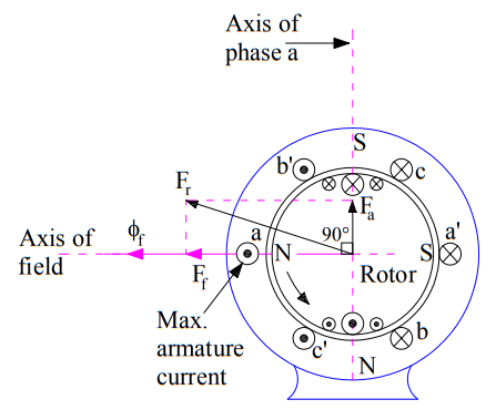
This armature reaction mmf wave produces North (N) and South (S) pole on the stator as shown in above figure. The interaction between these poles on stator and rotor causes the production of electromagnetic torque. For aa alternator, the prime-mover torque must counteracts this electromagnetic torque for conversion of mechanical energy into electrical energy.
Now, if we combine the space phasor of field mmf and armature mmf wave, then it can easily be seen that the armature reaction mmf lags behind the filed mmf by 90 degree. This is shown in figure below.
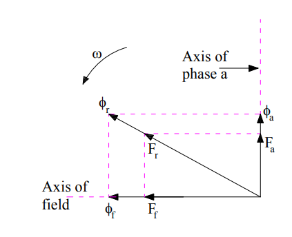
The resultant air gap mmf will be the resultant of filed mmf and armature reaction mmf. This means,
Fr = Ff + Fa
If we neglect the saturation, then the field flux Øf and armature flux Øa will be along their respective mmf wave. This is shown in the figure. Thus we can say that, armature reaction flux lags behind the field flux by 90 degree. Therefore, armature reaction mmf at unity power factor is entirely cross-magnetizing in nature.
Zero Power Factor Lagging Load:
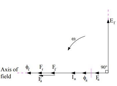
Zero power factor lagging load means that the load current is lagging behind the excitation voltage by 90 degree. This is shown in figure below.
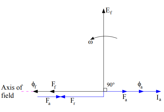
The above phasor diagram has been drawn using the following facts:
- The excitation emf lags the field mmf by 90 degree.
- As saturation is neglected, the filed flux will be along the field mmf.
- Armature reaction mmf is along the armature current.
From the above phasor diagram, it is clear that armature reaction mmf Fa is in opposition of field mmf Øf. This means that the resultant air-gap mmf will be equal to (Ff – Fa). Thus under zero power factor lagging loading condition of alternator, the effect of armature reaction mmf is purely demagnetizing.
This can also be understood in another way as described below.
Due to zero power factor lagging load, the current in phase “a” of armature winding will become maximum when the field poles have advanced by 90 degree in assumed counter-clockwise direction. This is shown in figure below.
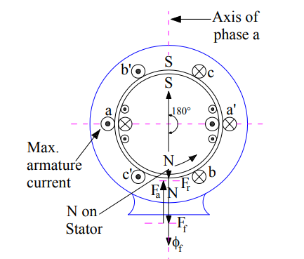
Carefully observe the above figure. It can be seen that, in this case the direction of armature reaction mmf Fa will be along the phase “a” axis and that of and filed mmf Øf will be vertically downward. This direction can be found by using right hand screw rule. Thus we see that, both the armature reaction and filed mmf are opposing each other. Hence, the effect of armature reaction mmf is purely demagnetizing in zero pf lagging load condition.
Zero Power Factor Leading Load:
The condition of zero pf leading load may be depicted by phasor diagram in the same way that for zero pf lagging load. This is shown below.
From the above phasor, it is clear that armature reaction mmf is in the direction of field mmf. Thus the effect of armature reaction mmf under zero power factor leading loads is purely magnetizing.
The above conclusion can also be drawn by analyzing the space phasor of the alternator. Zero pf leading means that the current in phase “a” of armature winding will be zero when the field poles are behind the axis of phase “a“ winding by 90 degree as shown in figure below.
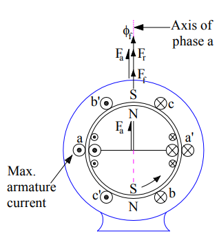
Therefore, the direction of field mmf and armature mmf will be same. Hence armature reaction mmf is magnetizing in nature.
Lagging Power Factor Load:
Lagging power factor loads are more common. So let us consider a general case of armature current Ia lagging the excitation voltage Ef by angle Ɵ. This means that the load power factor is cosθ.
For a lagging pf load having pf angle θ, the current in coil a and a’ will be maximum when the field poles have advance by θ degree in space. In other words, by the time armature current in coil a, a’ attains maximum value with the same polarity i.e. dot in coil side “a”, the rotor poles N, S would have moved forward by θ degree as shown in figure below.
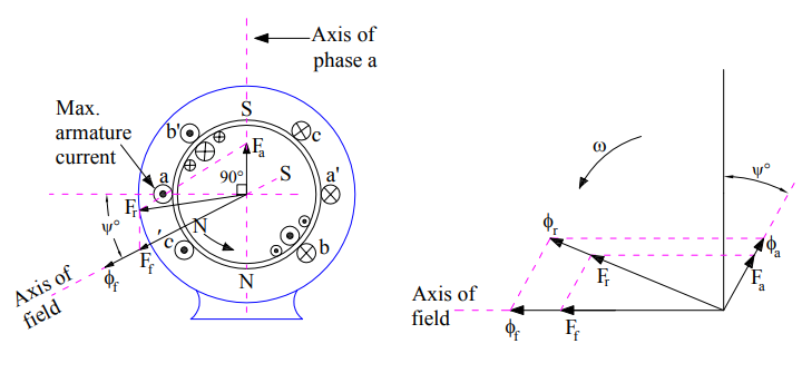
The resultant of rotating armature mmf Fa is directed vertically upward along the axis of phase “a”, because this phase carries the maximum current at the instant considered. Thus the armature reaction mmf Fa is lagging behind the filed mmf Øf by (90+θ) degree. Let us now draw the phasor diagram.
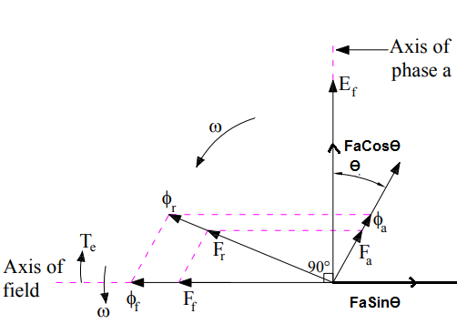
The armature reaction mmf can be resolved into two components: One along the excitation voltage Ef (FaCosθ) and another opposite to the field mmf Ff (FaSinθ). Thus we can say that, the effect of armature reaction in lagging pf load is cross-magnetizing as well as demagnetizing in nature.
Thus to summarize, the effect of armature reaction mmf on main filed mmf of alternator is tabulated below.
| Sr. No. | Loading Condition | Effect of Armature Reaction |
| 1) | No Load | No effect |
| 2) | Unity Power Factor | Cross-magnetizing |
| 3) | Zero Power Factor Lagging | Purely demagnetizing |
| 4) | Zero Power Factor Leading | Purely magnetizing |
| 5) | Lagging Load | Cross-magnetizing and demagnetizing |
Thank you! In case, you have any query please comment.
Thank you, this is very good explanation I found so far.
Thank you! Please share if you like the post.
explanation is nice . thanks
can u plz share me the vedio lecture of same content of what u have written above.
thanku
Thank you. Kindly share the post if you like it.