Class-B or Resonant Pulse Commutation is a forced commutation technique to turn off an SCR. In this technique, thyristor or SCR is turned off by gradual build-up of resonant current in the reverse direction i.e. from cathode to anode of SCR. This technique is also known as current commutation and occurs in DC circuit not in AC circuit.
Let us consider the circuit diagram for Class-B or Resonant Pulse Commutation for better understanding of the commutation process involved.
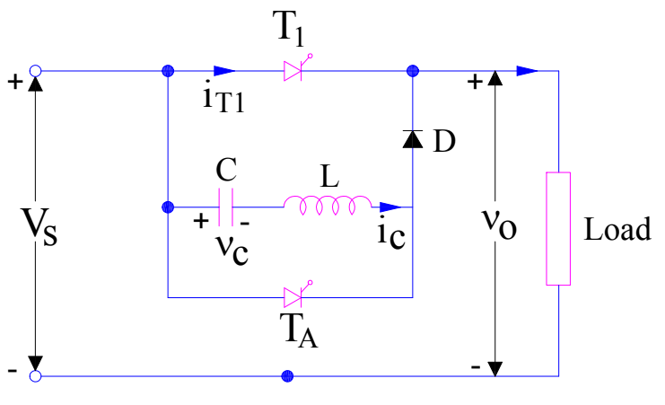
The commutation circuit comprises of Capacitor C, Inductor L and an auxiliary thyristor TA. Initially thyristor T1 and TA are in off state and capacitor C is charged to voltage Vs with left hand plate positive as shown in figure. Positive direction of capacitor voltage and capacitor current ic are shown in figure and taken as reference.
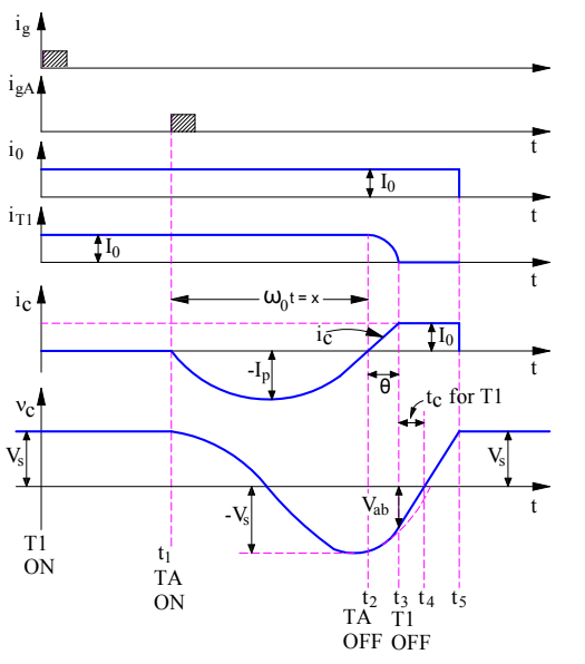
Now, at t=0, the main thyristor / SCR is gated and turned on. Load current equal to I0 starts flowing through the main thyristor T1 and Load. Now, we want to turn this thyristor off. To do this, we fire the auxiliary thyristor TA at t=t1. Till time t=t1, the capacitor is charged with source voltage Vs i.e. vc = Vs, capacitor current ic = 0 and current through main thyristor T1 i.e. i0 = I0. This is shown in figure below.
When auxiliary thyristor TA is fired, it starts conducting and provides a path for the discharge of capacitor C. L, C and TA forms a resonating circuit. The resonating current ic for this circuit is given as
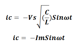
Negative sign in the above expression of resonating current is given as the actual current flows in a direction opposite to the direction of current ic shown in the first figure.
Carefully observe the waveform of ic. It can be seen that, after half cycle, the value of ic reduces to zero at t=t2. This means, the current through the auxiliary thuristor TA reduces to zero. Let’s check if the auxiliary thyristor gets reversed biased after t=t2. Why are we checking this? This is because, the current through TA is zero at t=t2 and if it gets reversed biased after t=t2 then TA will get turned off. The voltage across TA equals the voltage across capacitor. The expression for capacitor voltage can be calculated as
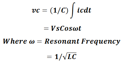
From the above expression of voltage across capacitor, if we put ωt = π then value of Cosωt will -1. This means, the capacitor voltage will get reversed after half a cycle of capacitor current i.e. at t=t2. Thus, the auxiliary thyristor TA is reversed biased after t=t2. Hence it will get turned off at t=t2.
Now, TA is OFF and capacitor C is charged up to source voltage Vs with its right hand plate positive. This means, the diode D is now forward biased and hence resonating current ic will now flow through least resistive path i.e. through C, L, D and main thyristor T1. But this resonating current ic will flow through the main SCR T1 from cathode to anode i.e. in reverse direction. This simply means, the current I through the main thyristor T1 will be given as
I = I0 – ic
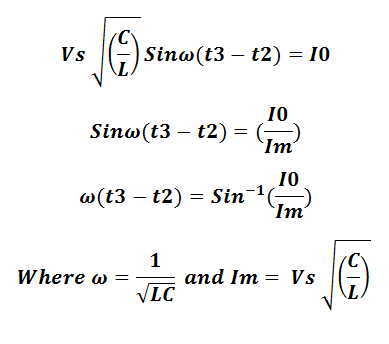
When the magnitude of ic reaches I0, the current through the SCR T1 will become zero. This can be seen at t=t3. Now, you might ask, when the resonating current will attain a value of I0? This can easily be calculated from the equation of the resonating current. Let’s find it.
Now, at t=t3, the current through the main thyrsistor T1 is zero. Let’s check, if it is reversed biased at this instant of time. Again, the voltage across the main SCR T1 at this instant of time (t=t3) is equal to the capacitor voltage. The capacitor voltage after ωt = π is negative. This means, the right hand plate is positive whereas left hand plate is negative. Hence, the main thyristor T1 is reversed biased. Thus, main thyristor T1 will turn off at t=t3 as the current through it is zero and it is reversed biased after this instant of time.
From the above discussion, it should have been clear that the peak value of resonating current ic i.e. Im in the expression of ic, must be more than load current (I0) for reliable commutation of thyristor / SCR. As SCR is commutated by the gradual build-up of the resonating current ic in the reverse direction of SCR, this method of commutation is called the current commutation, resonant pulse commutation or Class-B commutation.
Let’s now check what happens after the commutation of main SCR T1. Once the main SCR T1 is turned off, load current I0 begins to flow from source Vs to load though C, L and D. This causes capacitor C to charge linearly from Vab to zero at t = t4 and then to source voltage Vs at t=t5. At t=t5, the capacitor is charged up to source voltage Vs with its left hand plate positive. Therefore, capacitor will not allow the flow of load current after t = t5.
The circuit turn off time is equal to the time period for which the main thyristor / SCR is reversed biased. Here, this time period is (t4 – t3). Therefore,
Circuit Turn Off time tc for Class-A commutation = (t4 – t3) = (VabC) / I0.
Good