Class-D Commutation is a commutation method used to turn off thyristor in a DC circuit by the application of a sudden reverse voltage across the terminals of SCR. This is the reason, it is also called Impulse Commutation.
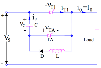
A Class-D commutation circuit consists of Main Thyristor T1, Auxiliary Thyristor TA, Capacitor C, Diode D and Inductor L. Load current I0 is assumed to be constant throughout the discussion. Let us consider the commutation circuit shown below for better understanding. Reference direction of capacitor current and capacitor voltage is shown in figure.
Initial Circuit Condition:
- Main Thyristor T1 and Auxiliary Thyristor T2 are in OFF state.
- Capacitor C is charged up to source voltage Vs with its upper plate positively charged.
Class-D Commutation Technique:
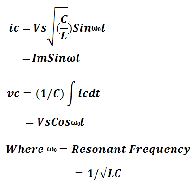
With the above initial condition, when main SCR T1 is fired or gated at t=0, main thyristor T1 becomes ON and load is connected to the source through T1 and hence, load current I0 starts flowing. Another circuit comprising of Capacitor C, T1, L and D is formed. This circuit is a resonating circuit. A resonating current ic starts flowing through this circuit. Due to the flow of the resonating current, capacitor C starts to charge in opposite direction. The value of resonating current and voltage across the capacitor is given as below:
Due to this resonating current, the current through main thyristor T1 at any instant of time is equal to the sum of load current I0 and ic i.e. (I0+ic). The waveform of resonating current and voltage across the capacitor is shown below:
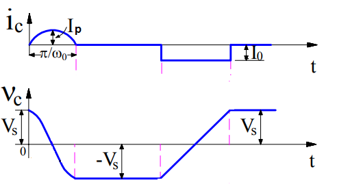
From the above current waveform, it is clear that after t = (π / ω0), the resonating current becomes zero and Capacitor C gets fully charged up to source voltage Vs but in opposite direction. This means, after t = (π / ω0), lower plate of capacitor is positive while the upper plate is negative. It should also be noted that, after t = (π / ω0), as the diode D gets reversed biased, no resonating current will flow. This means, the current flowing through the main thyristor will become I0. This is the reason, ic is shown zero after t = (π / ω0).
Now, we want to turn off main thyrsistor T1. We will we do? The auxiliary thyristor TA is fired at t=t1. As soon as auxiliary thyristor TA gets ON, a sudden reverse voltage equal to the capacitor voltage is impressed across the main SCR T1. Due to this, the current through main SCR reverses momentarily to recover the stored charges. Due to this recovery of stored charges, the current through the main SCR T1 gets quenched and it gets turned OFF.
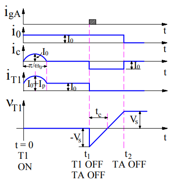
Let’s see what happens after turning OFF of main SCR T1. Once main thyristor T1 gets OFF, constant load current starts flowing through Capacitor C and Auxiliary Thyristor TA (as it is still ON). Due to this load current, the capacitor gets charged from –Vs to +Vs. As the load current is constant, this charging of capacitor from –Vs to +Vs is linear. When capacitor charges to +Vs, it will not allow any further flow of load current. Thus current through Auxiliary Thyristor TA becomes zero and it gets turned OFF. During the time TA is ON i.e. from t=t1 to t=t2,
Voltage across main thyristor VT1 = Voltage across capacitor
= -vc
Load Current I0 = Capacitor Charging Current
= -ic
Negative sign is used for voltage and current as it is opposite to the reference direction shown in circuit diagram. Circuit turn off time is tc.
Class-D commutation is also known as Auxiliary Commutation due to the fact that Auxiliary Thyristor is used for the commutation of main thyristor. When auxiliary thyristor is ON, capacitor gets connected across the terminals of main thyristor, therefore this method of commutation is also called Parallel Capacitor Commutation.